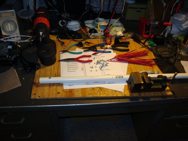
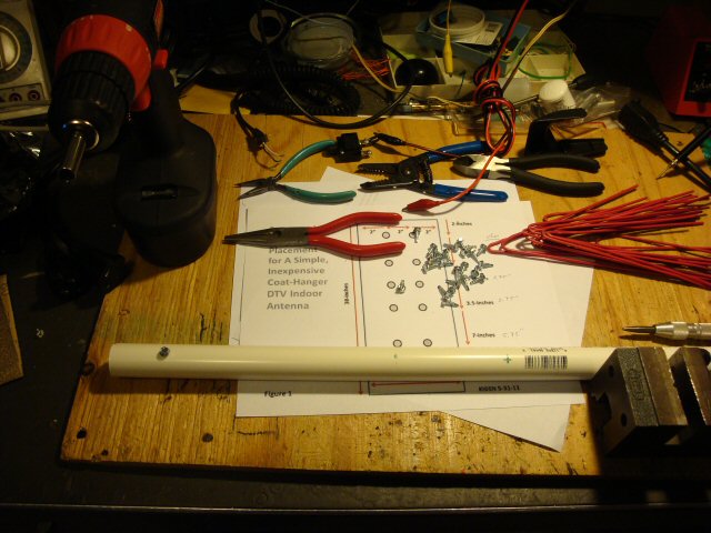
Parts and Tools
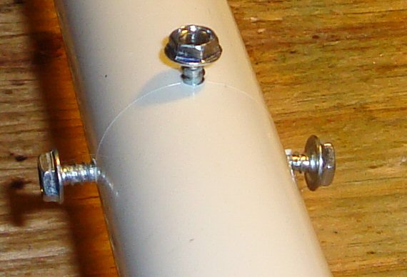
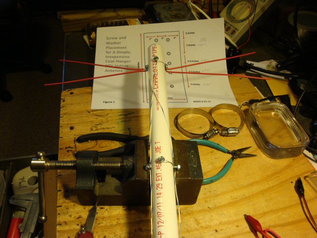
The Score-Line & Screws
Wiring Diagram
| NOTE: The easy way to wire this correctly is to start by connecting all the FRONT elements to all the related RIGHT elements, then all the BACK elements to the related LEFT elements. Then connect the phasing wires that crosses over twice. |
First Element and Wire
Four Elements Attached
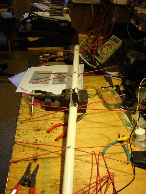
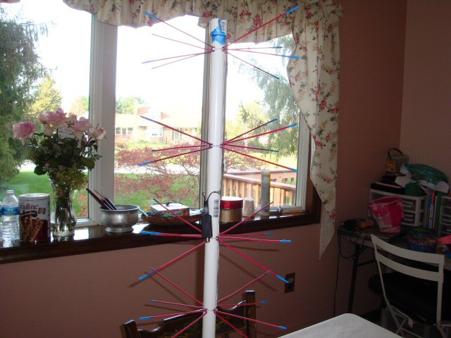
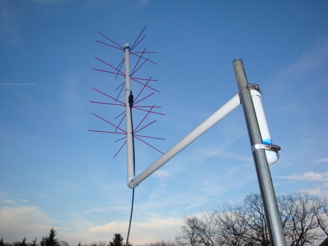
Alignment of the finished Antenna Elements
This antenna has 360 degree coverage and it is horizontally polarized with gain because
of the four elements. This antenna is made up of four dipoles each of two quater wavelength
sections of about 7.5" each for a total length of about 15". In this photo you can see the
alignment of the elements from top to bottom.
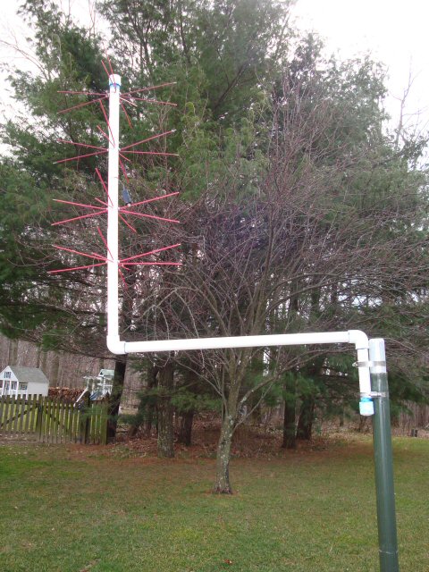
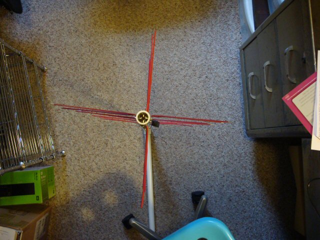
The Finished Antenna sitting on the floor."
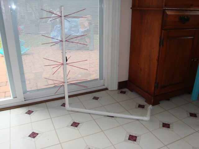
The antenna is being held up by its mounting pipes. The only difference is that I rotated the
bottom 3" section horizontally so it helps support the antenna while resting on the floor.
In the final installation the 3" section will be pointing down and it will be used to
hold the antenna to the antenna mast with two hose clamps. See photos below to see this.
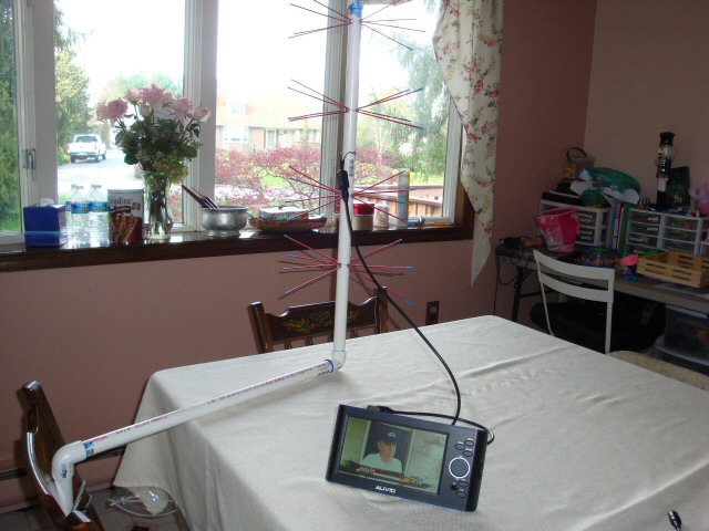
Kitchen Table Test Sort Of East To Baltimore
Kitchen Table Test Sort Of South To DC
Aurora and the Missing Transformer, an Empty Case
You can see here that Aurora is holding the case of the 300 ohm to 75 ohm transformer but
the transformer has been removed and wires soldered into the case to make contact from the
300 ohm twin-lead wire to the cable type F connector. I have found that this method works
better than the "bad" transformers and a little better than the good transformers since there's
no conversion loss.
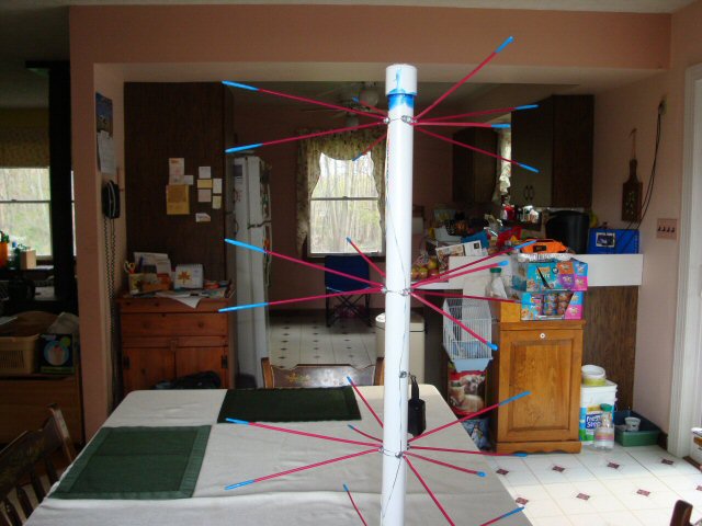
The Kitchen Table Test
I tested the antenna while it was sitting on the kitchen table with the elements pointing
somewhat south to Washington D.C. and somewhat east pointing twords Baltimore. The arrangement
allowed full reception of all Baltimore stations, 2, 11, 13, 24, 45, 54, and 67 as well as a
few Washington stations, 4, 20, and 32 but only 20 was received well, and then last the Ion
station, Ch 66, from Manassas VA.
OutsideTest.JPG
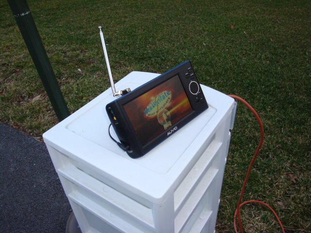
Close Up Outside Test
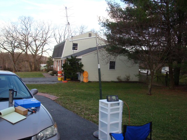
The Whip Antenna Test Setup
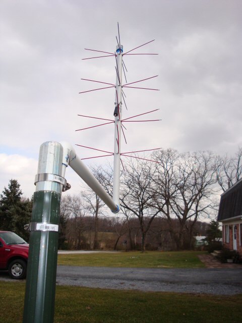
Mounted Antenna #1"
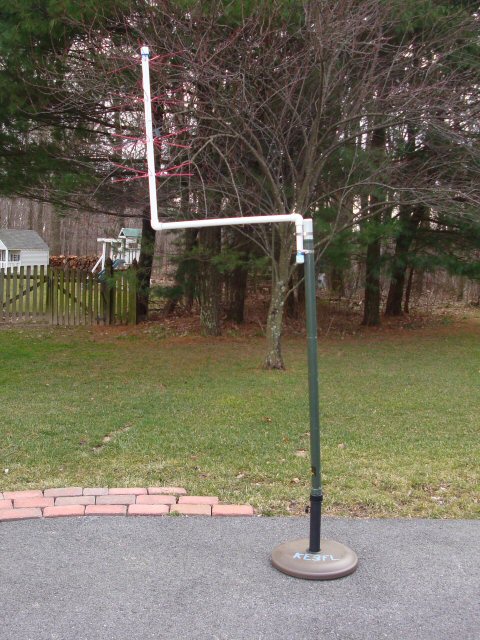
Mounted on an antenna mast sitting on the driveway.
Mounted Antenna #2"
The last task of this project will be to protect all exposed wires and
then to paint the antenna.
Mounted Antenna #3"