FM Antenna Replacement, by KE3FL
I bought a some AM/FM pocket radios from sciplus.com. You may still be able to see this product on their web site at: Retro-style transistor radio Here's what it looked like just out of the box: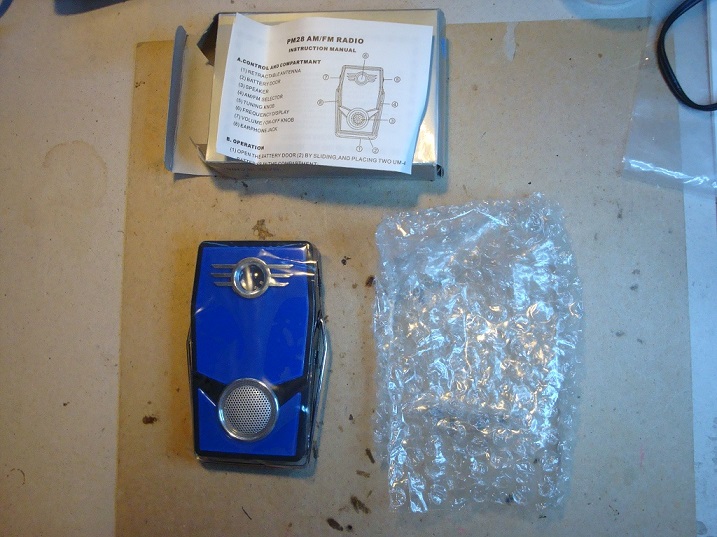
Photo 1: Shows the box, user Instructions sheet, radio, and packing.
When it arrived I tried it out for a few days and decided to keep it. However, this is not an easy radio to use. By that I mean that if you buy one of the newer AM/FM radios today you will find that many in the higher price range have digital tuning. Still most of the lower price range radios have a nicer and easier –to-use tuner and frequency scale.
The tuning of this radio took me some time to get used to. The tuning dial is stiff and it is difficult to find a frequency. It still takes me a little time to locate a station and get it tuned in as best I can.
However on AM it has plenty of sensitivity and volume.
The FM band receiving leaves much to be desired. This is because the FM antenna is actually a metal kickstand going around the radio which can be seen in photo 2:
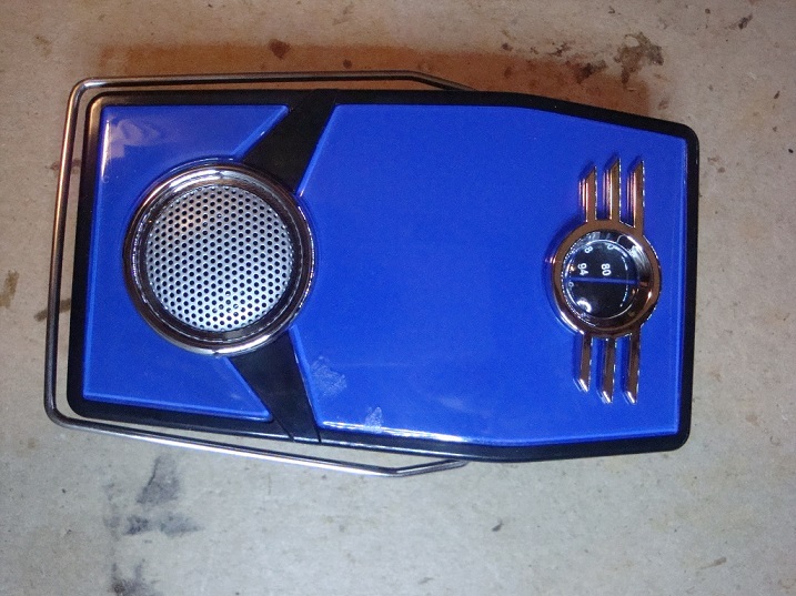
Photo 2: Closeup of the radio and the kickstand FM band antenna.
I first tried to make the FM band which is easier to tune in and listen to by using an alligator clip lead to extend the antenna. This worked very well and is really all that is needed to get it to be sensitive and to have the volume needed for easy listening. One just has to clip the wire to any place on the kickstand and hang it vertically. I found this to be a problem most of the time. The first thing I did not like about this antenna is that it always seemed to be in my way and the second problem was that it simply did not work as well as I would like, a flexible wire does not stay vertical on its own.
I decided to look for another way, perhaps even to add a telescoping FM radio antenna to the radio. This called for a look inside the radio to see how the kickstand antenna was connected to the radio circuit and how much room there was to work with inside. This connection can be seen in the next photo #3:

Photo 3: This shows a good first view of the inside of the radio. It also shows a good view of the kickstand AM band antenna resting on its connector on the left under the tuning wheel.
The kickstand antenna is connected on the right side just under the tuning wheel. It is a simple press fit resting on a springy bent piece of metal with a foam rubber pad inside the bend. I assume this was to help keep the metal springy enough to stay in contact with the kickstand antenna.
On seeing this I decided to try and see if I could find something that would fit in that space and not interfere with the case.
The kickstand can be removed by simply lifting it out. This revealed the small space available for a new connector, seen in photo 4:
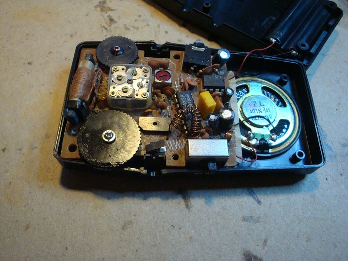 Photo 4:
A closer look at the kickstand antenna connector.
Photo 4:
A closer look at the kickstand antenna connector.
If you look closely, you can also see the kickstand support just before the circuit card. It is also part of the case in black plastic. It's much easier to see after the circuit card is removed in photo 5:
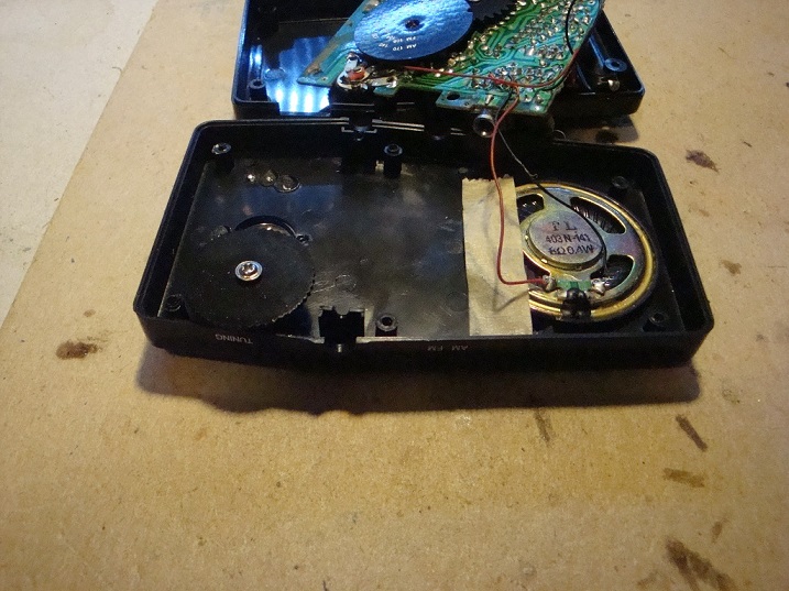 Photo 5:
Circuit card moved out of the way in order to remove the
kickstand support.
Photo 5:
Circuit card moved out of the way in order to remove the
kickstand support.
This support was now easy to remove by cutting it out with a good pair of small wire cutters as shown in photo 6:
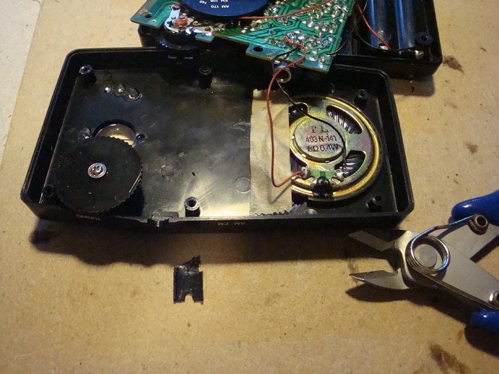 Photo 6:
The removed kickstand support that is in the way and no longer needed.
Photo 6:
The removed kickstand support that is in the way and no longer needed.
I then tested the hole to make sure the 3.5mm mono socket would fit. It did but I had to remove the side rail of the socket. That was used to break a connection so as you plug in the headphones, the sound would no longer go to the speakers. That feature is not needed since only a simple single contact connection is needed. I ended up shorting both the tip and barrel connections together. Again (We only need one connection to the antenna). Photo 7 shows the preliminary placement with the removed rail and wired to the original kickstand antenna connector.
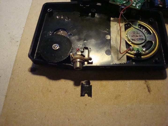
Photo 7: Test placement of the monaural earphone socket as the new antenna connector.
I put the circuit card back in and the connection from the original press-fit antenna connection was used as a solder pad to attach a wire that goes to both the barrel and tip connections on the monaural earphone socket.
This can be seen in photo 8:
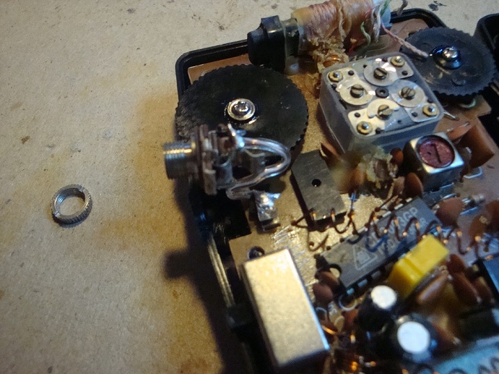 Photo 8:
The first successful monaural earphone socket attached directly
to the kickstand antenna connector.
Photo 8:
The first successful monaural earphone socket attached directly
to the kickstand antenna connector.
Then I tried to close the case and found that I had to rotate the earphone socket to get a good no-interference fit. The case then closed as designed.
I did this to two radios. The first one is shown in photo 9 where the radio, the new telescoping antenna, and the old kickstand antenna are shown:
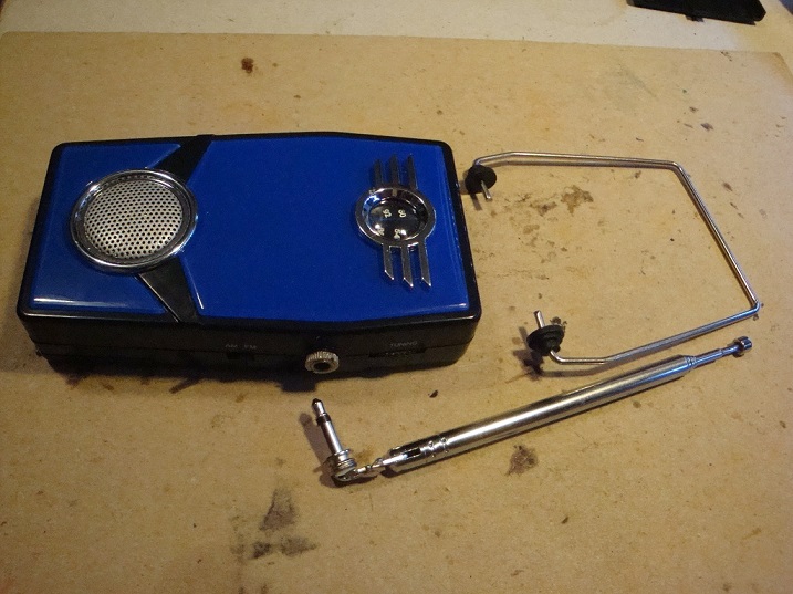 Photo 9:
All closed up with the new earphone-antenna connector and a new
telescoping FM band antenna attached to a monaural earphone plug.
Photo 9:
All closed up with the new earphone-antenna connector and a new
telescoping FM band antenna attached to a monaural earphone plug.
The second radio I did a little differently. The press-fit antenna connection was broken off and the wire for the earphone socket was attached to the underside connection solder pad. That pad was use for the connection to the press-fit antenna connector. This can be seen in photo 10:
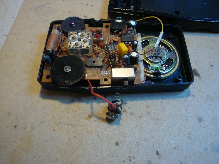 Photo 10:
The second successful monaural earphone socket attached to the
original FM band antenna connection and the spring-loaded
antenna connector removed.
Photo 10:
The second successful monaural earphone socket attached to the
original FM band antenna connection and the spring-loaded
antenna connector removed.
I found this a fun project and the two radios now work as well on FM with either the telescoping antenna or a longer wire also attached to a 3.5mm monaural earphone plug.
KE3FL Home Page