Fldigi on the Cheap, by KE3FL Last update: 11/16/2020
Tests from 05/05/2020 - 05/21/2020. What is fldigi? Fldigi is a free, open-source program intended for Amateur Radio Digital Modes operation using a sound card in a personal computer. You can read more at: W1HKJ beginners page or fldigi on wiki as well as many other web sites.Now what do I mean by “cheap” ? Well, the cheapest for me was to use the speakers and microphones from the radio and computer to do everything needed to get on the air using fldigi. I already had two mics for the computer and the first one I used worked fine.The mics were used to pick up the fldigi sound for whatever digital mode was selected, and then to either decode it (using the fldigi program on my computer) or to transmit it over my radio. A more expensive way to work fldigi is to buy a cable that goes from the digital-mode-ready radio to the computer running the fldigi program.
I wanted to reduce the digital communications noise for as little out- of-pocket expense as I could. So, I started thinking about how to do this on-the-cheap: my time and effort plus what I already had on hand in my junk box.
I started by using a cable from the FT-8900 external speaker port to my computer. I tried two different circuits I found on-line, but neither produced enough audio level for the computer to be able to use it. I then tried turning the radio’s audio level way down and bringing it up slowly while the audio cable went from the radio audio external speaker output directly into the computer’s audio input port. This worked fine for my laptop's sound card audio input.
For the computer-to-radio audio connection I originally wanted to bring all mic and PTT connections out from the FT-8900 mic port, but tests showed that the inputs to the port (from the mic) were not directly from the mic element or the PTT switch. There was some circuitry involved.
My second choice was to connect to the correct mic lines inside the mic where I found a circuit card. Also, while the PTT inside the mic gets shorted to ground, this is not what comes out on the PTT line to the radio. This being the case, I decided to simply use the PTT switch in the mic at this time to get the project done more quickly. I figured a switch could be installed later if I decided it was needed. In the meantime I'm using a rubberband to hold the PTT on, as needed. This was a method I used on my walkie-talkies as a kid to "spy" on my sisters conversations. While it worked, I never did learn anything useful.
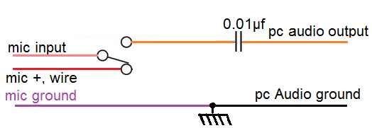 Radio mic wires to PC Audio Output
The Mic circuit was also on the card so I pulled the positive mic line (red) off the card and took that circuit card connection (now a pink wire) the mic positive line (a longer red wire) and the ground connection (a purple-wire) out to a switch to select from the mic line (red) or the PC audio output line to a 0.01 μf cap, then to the mic input to the circuit card positive line (pink).
The radio's external speaker output is going to a switch to the external speaker. This switch is now a SPDT On-Off-On switch. One on-position is for full speaker volume, the other on-position is the low speaker volume going through a 52 Ω resistor. The center position shuts off the speaker. The radio's speaker output also always goes full volume to the PC center (tip) audio input line. The ground wire from the mic circuit card goes to both the PC audio input and the external speaker common lines.
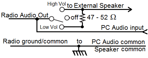
Radio Speaker Output to External Speaker and/or PC Audio Input, Schematic
NOTE: This schematic shows the final design being used. In the photo below, "Radio Speaker Output to External Speaker and/or PC Audio Input, Photo" you will see two capacitors that I originally used but which have been removed and the third port, another output to the PC, is no longer used so it is also no longer shown in the above schematic.
Once this was done, I tested this setup during our weekly fldigi emergency group net. I found that not being able to hear anything from the computer meant I had to pay attention to the PC screen to see when the fldigi transmission was over. I added a 52 Ω resistor to the SPDT switch as described above. This was much better, and allows me a low volume so I can hear, and the option of switching the external speaker off.
NOTE: Switching between volumes during the receiving of a digital message is not recommended because it will interrupt and send random characters into the message or picture.
The wiring for the mic shows the wires added to the mic and coming out a small hole, ground out, of the mic case.
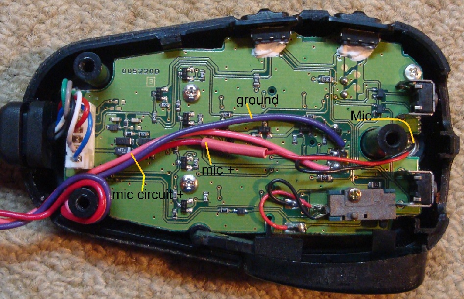
Microphone Modifications, Mic or PC input to the mic Circuit
For the wiring for the external speaker, I used a little audio splitter box I had created when I was proctoring tests for the Novice, General, and Extra CW Exams. The input cable to the box goes into the FT8900 external speaker output port and then the three output ports are for the external speaker. The left side port is seen with the capacitor attached to the SPDT switch and the center port is for the output from the radio to the input audio port of the PC. The right side port was an experiment to cut down on the output port's power to the PC, but this didn't supply enough audio for the PC so I simply plugged the PC cable into the center port and that worked fine for the PC.
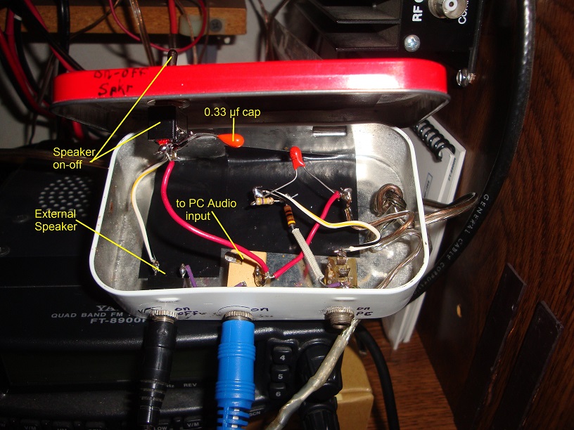
Radio Speaker Output to External Speaker and/or PC Audio Input, Photo
I hope you can use this or a take-off of it if you have two SPDT switches and at least the 0.01 μf capacitor for the audio from the PC to the mic positive input.
Philip Karras, KE3FL