|
uBITX Electret Microphone
Started: 04/01/2019 Last Updated:
To view larger images click on the image you wish to see larger.
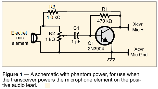
The circuit I used to build this microphone was taken from a recent article in QST with one modification: The uBITX mic element, is an electret mic element, not a dynamic element and it needs a biasing voltage to drive the mic element. I looked up other electret mic elements and how to bias them and found that in the past I'd used some from Radio Shack. Those needed a 1K-Ohm biasing resistor, so a 1 K-Ohm resistor was added. You will also notice that I used a longer 1K-Ohm variable resistor for the transistor amplifier. There were two reasons for this: (1) this resistor is more accurate than a smaller pot would be, and (2) I have more of them than the smaller ones. I figured that if it didn't fit into the case I intended, I could always swap it out and use a smaller pot. I considered that the 1K pot should probably be put at its center value, or about 500 Ohms for each side, and I would then adjust the gain while outside a case. Once satisfied put it into a case. As it turned out, this value seems to work rather well. While it may be able to be improved a bit, I thought the overall quality and volume was fine during my tests. This may change as I have SSB QSOs and get reports from others. The image/schematic below comes from QST December 2018 Page 53 of Hints & Hacks, and is used with permission. The one change/addition which was needed was the 1 K-Ohm, R3, resistor. This resistor is needed to bias the electret mic element and, without it (as I discovered when I forgot to include it), the mic does not work at all. The original article was by Paul Dobosz, K8PD and, as mentioned above, was for a dynamic mic element.
The recordings were made using the SDRPlay radio-and-receiving program. The radio was connected to a dummy load with a wire attached to the dummy load. The SDRPlay radio was also connected to a length of wire and placed close to the wire connected to the dummy load. Both lengths of wire were looped and the separation between the two loops of wire was about 12 inches.
A whistle was noticed when testing with the mic inside the case. This whistle sounded like a noise heard on an AM radio near my battery desulfator circuit when it is working. Sure enough, a check showed that the desulfator was operating and was the cause of the whistle. A choke was tested on the power cord close to the radio's power input port. This test was done while the desulfator was still working. It sounded like the choke removed about 95% of the whistle so it was left on the power cord just in case the desulfator was still connected when operating the uBITX radio. Please note that I've been testing out this "desulfator" circuit to see if it actually helps maintain my Lead acid batteries. The best article I've come across was on Wikipedia and two people have added comments that the method is not helpful or scientifically proven to work at all. You can read the comments at the beginning of the article at: Talk:Battery regenerator If you want to try and build such a circuit you can also read the article at: Battery Desulfator Concept and Design Explored At present I have no evidence that the circuit I have works to rejuvenate a dead lead acid battery any better than charging the battery does. It might help a little, meaning I can start the mower for another time or two, (and that could all be due to having to charge the battery as well anyway) but in the end I've still had to replace every battery I've tried it on. Phil Karras 04/01/2019 Return to the: |