 Return to:
previous page
Return to:
previous page
|
Problem:
Even with a new battery (Li 2032 coin size battery) the units don't
work. These units were about six years old when three of the four
we were using started having problems. These three became intermittent
at first and then all three failed completely.
RF Information: This device operates at ~ 315 MHz Other Information: In general, the larger button is used to open the garage door and the two small buttons can be programmed to turn the door lights on/off. Tests: I first suspected that the mini-temporary contact switches were getting dirty or becoming defective since these were mechanical. After changing one of the temp switches of one of the units, I found that this did not help. Quick continuity tests of all the switches of all defective units was performed and all switches were found to be working fine. The next electro-mechanical point of possible failure were the battery holders. I tried an external power supply adjusted to 3.0 Volts and clipped onto the battery holders of all three units. This had various levels of success: one unit worked perfectly every time; the other two were, at best, intermittent. This was better than anything else tested, so a further test was performed on all three units. These battery holders hold two batteries in series for a 3-Volt power source. I used the part# BH-42 from http://www.allelectronics.com, a battery holder with short wire leads. I then tried all units and found them to all work perfectly. I added a Velcro strip on the back of the battery holder and on the front of the case so the battery holders would not drop when the visors were used. The bottom line is that all "defective" units were in fact working perfectly except for some kind of battery holder electrical problem. I did not bother testing, cleaning, or re-soldering the battery holder connections since I liked the idea of using more powerful batteries which were external to the case, making battery replacement easy. If you have similar problems with your remote garage door openers I'd try cleaning, re-soldering the battery holder, and as a last resort, using an external battery holder soldered onto the circuit card power connections to see if this solves your problems. Update, 03/10/2019: RF Information: My best reception so far is ~ 315.5 MHz using Wide Frequency Modulation, WFM. NOTE: Finding the frequency of your units would be better done before any transmitting problems occur with the board. Listened to the transmission using WFM no differences were found between the units I have, as long as I could get close enough to the circuit card. When they transmit all units seem to send seven bursts of data. More problems! Now one of the fixed units is again not working. The batteries were tested at 1.40 and 1.44 Volts, and taking the unit apart showed both wires still firmly attached. So, at this point the problem is not the battery holder, batteries, or the connections. After the unit warned up a bit to ~ 55 degrees F the unit started working again. This will be a continuing issue until I can find why it doesn't work when the temperature is in the 30's. |
|
After measurements, and testing I found a second problem with at least
one of the four boards I examined. This board would work whenever I had a
multimeter probe on one of the leads of the surface mount Transistor Q2.
I decided to resolder these connections and this seems to have fixed the
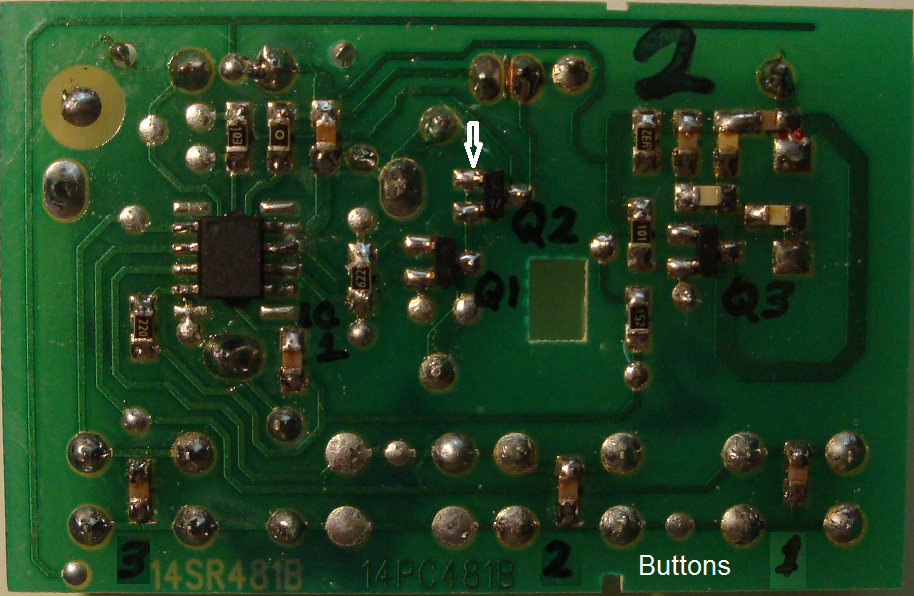
intermittant transmitting problem. In the image below:
"Solder Side of Circuit Card"
Q2 is in the middle of the three transistors.
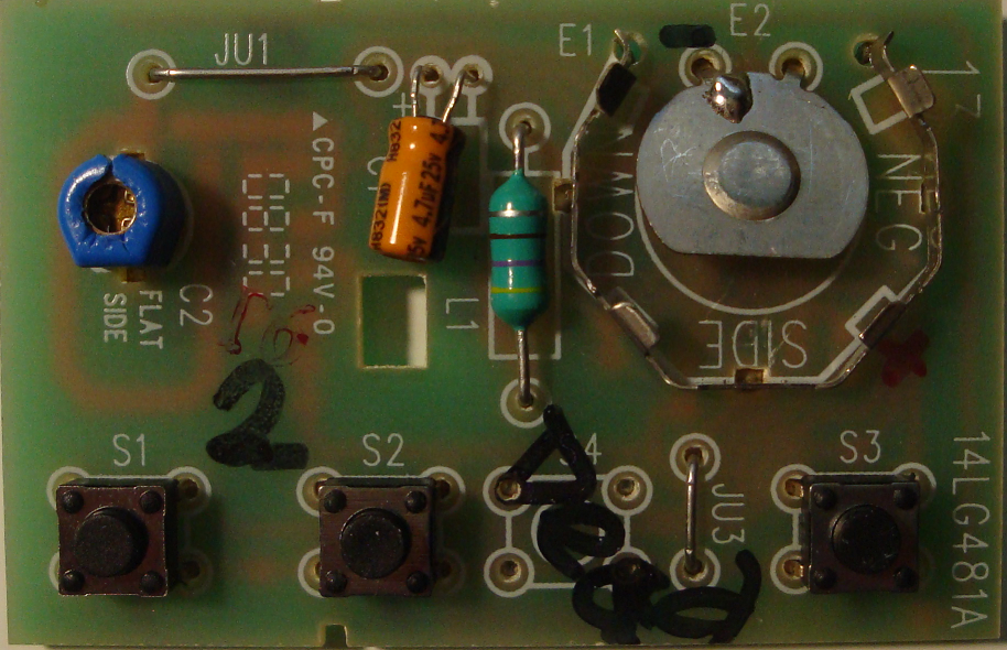
When I placed the probe on the top left leg of transistor Q2 then all buttons would send a signal that turned on/off lights or lifted/closed a door. I resoldered all three connections of Q2 and then tested without a probe and all three buttons continued to worked as programmed. I believe that at least one or two more boards have the same kind of issue, an intermittant connection someplace. Only time will tell if I can find the problem(s). I've already killed board #2, see image below, "Button Side of Circuit Card" while connecting it to too high a voltage from my power supply. The IC seems to be partially shorted drawing ~230 mA when not being used. |
 Return to:
previous page
Return to:
previous page