Adjustable Add-On Power Supply
Started: 11/1/2019 - Last update: 06/30/2020
This project started when I was looking at my Astron Power supply that I use in
the garage for various jobs, recharging batteries, running ham radios, running
a DC battery drill, and running other things, and thinking that it would have
been nice if the Astron could also have an adjustable output voltage for things
that don’t require 13.8 Volts, or even, if possible adjustable to up to 24 Volts.
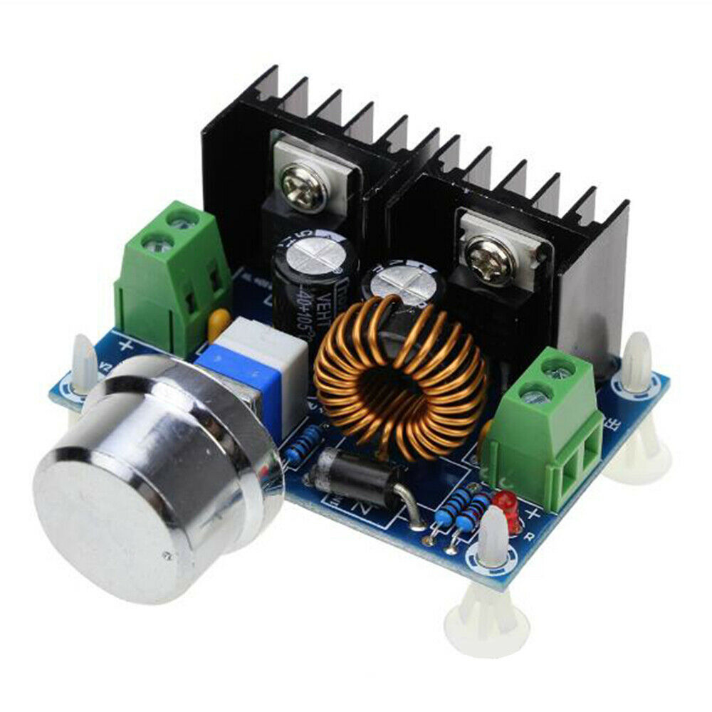
With this in mind I went web diving to search for adjustable power supplies and I came across the following description: “DC 4V-40V to 1.25-36V Buck Converter 200W 8A Module” which I thought would change any input voltage from 4V to 40V into any output voltage from 1.25V to 36V. So I thought WOW I could change 13.8V into anything from 1.25 to 36V up to 8Amps (assuming the input power supply could supply the needed power (V*A). So, the Astron 13.8V 20A supply is up to 276 Watts, and that would mean ~ 24V up to 10Amps, well only 8 because a few things like losses and the module only claims 200W and a max of only 8A.
Unfortunately I got it wrong, a buck converter is only able to adjust the voltage up to a max of the supplied input voltage, or less. It does NOT buck the voltage up higher than the supplied input voltage.
If you want to find a buck converter try searching on, “Buck Converter 200W 8A Module” or leave off the power/amp limits and you’ll find versions up to 12A.
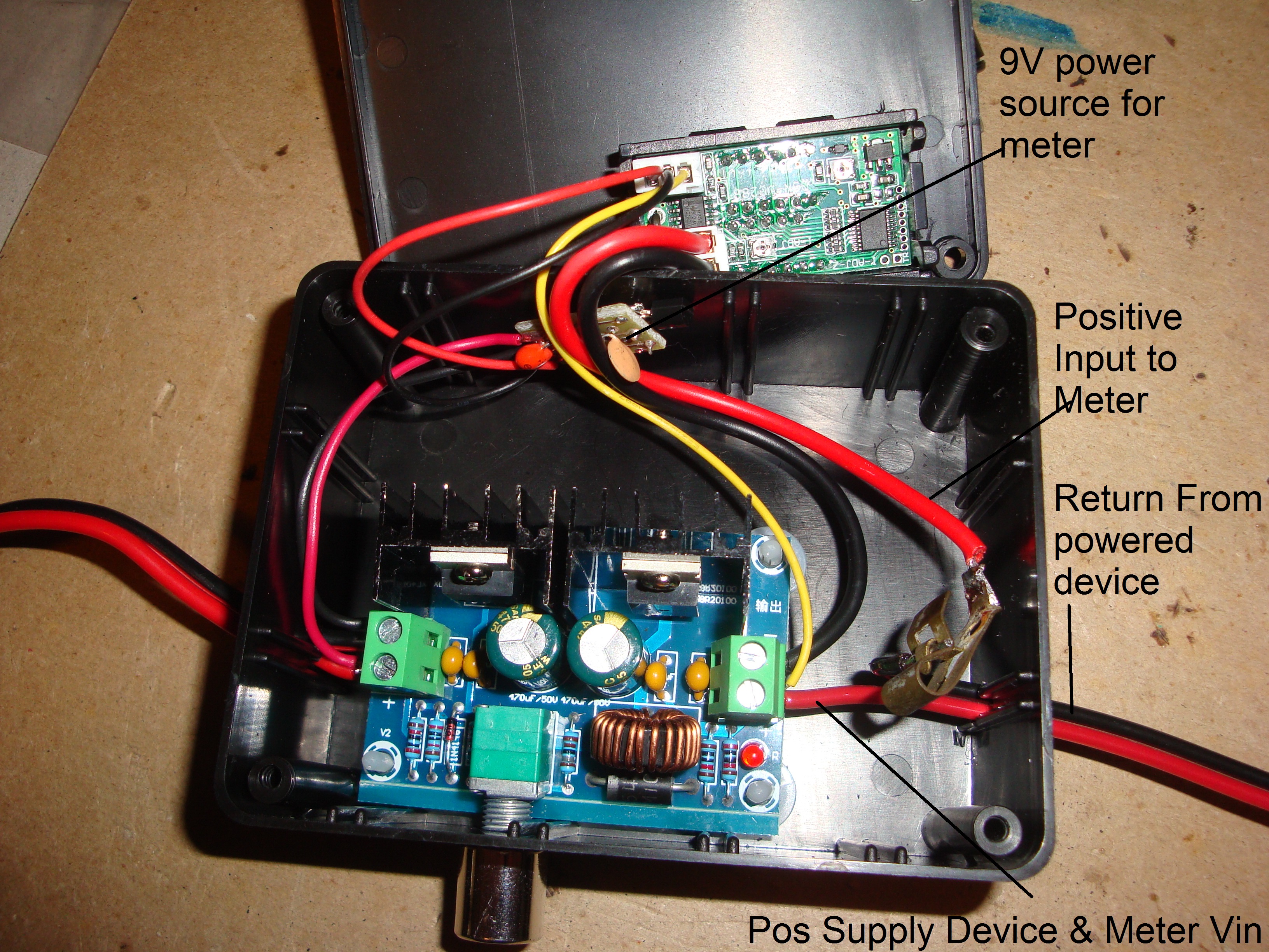
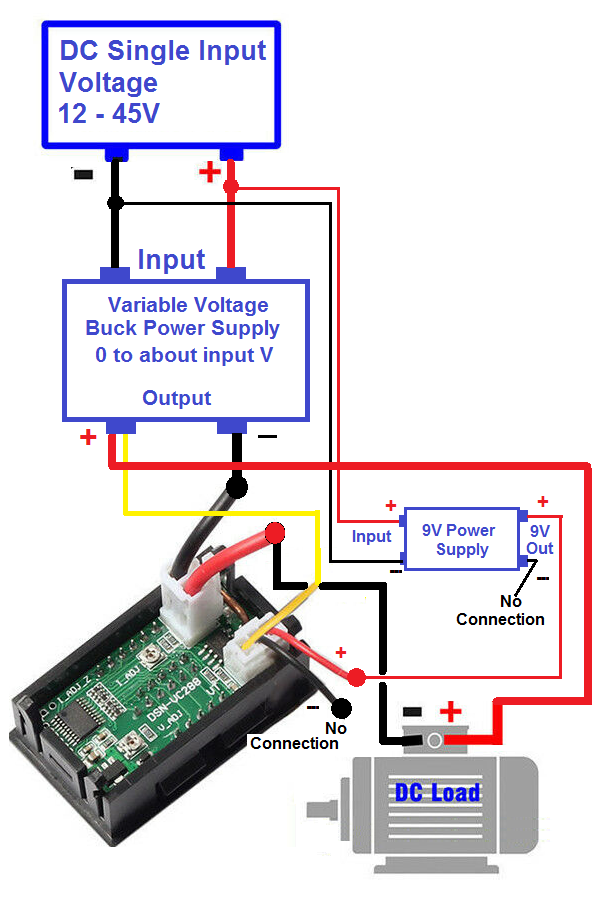
I then found and bought a few Volt & Amp displays. The ones I bought required a minimum of 4 Volts to operate. I wanted to see down to the lowest Voltage so I built a 9V 100 mA supply using a small 7809 regulator. If you want to find the displays on eBay try searching on, “Digital LED DC Voltage/Current Display/Meter” See the image …
I wanted to be able to replace any of the parts/boards so I modified a few things to allow all wires coming in to be either screwed or clamped to other wires or boards.
I added the output wires and the display with a clamp soldered to the display’s positive current wire. The display was attached to the top cover.
Pleas note that the wiring I used is different from that originally tried. The black wire from the display no longer returns to the power source. I noticed a ground-loop problem when I attached this wire to the 9V supply return. When I cut it the current and Voltage read much closer to the actual values. When it was connected the current was reading 70% too high!
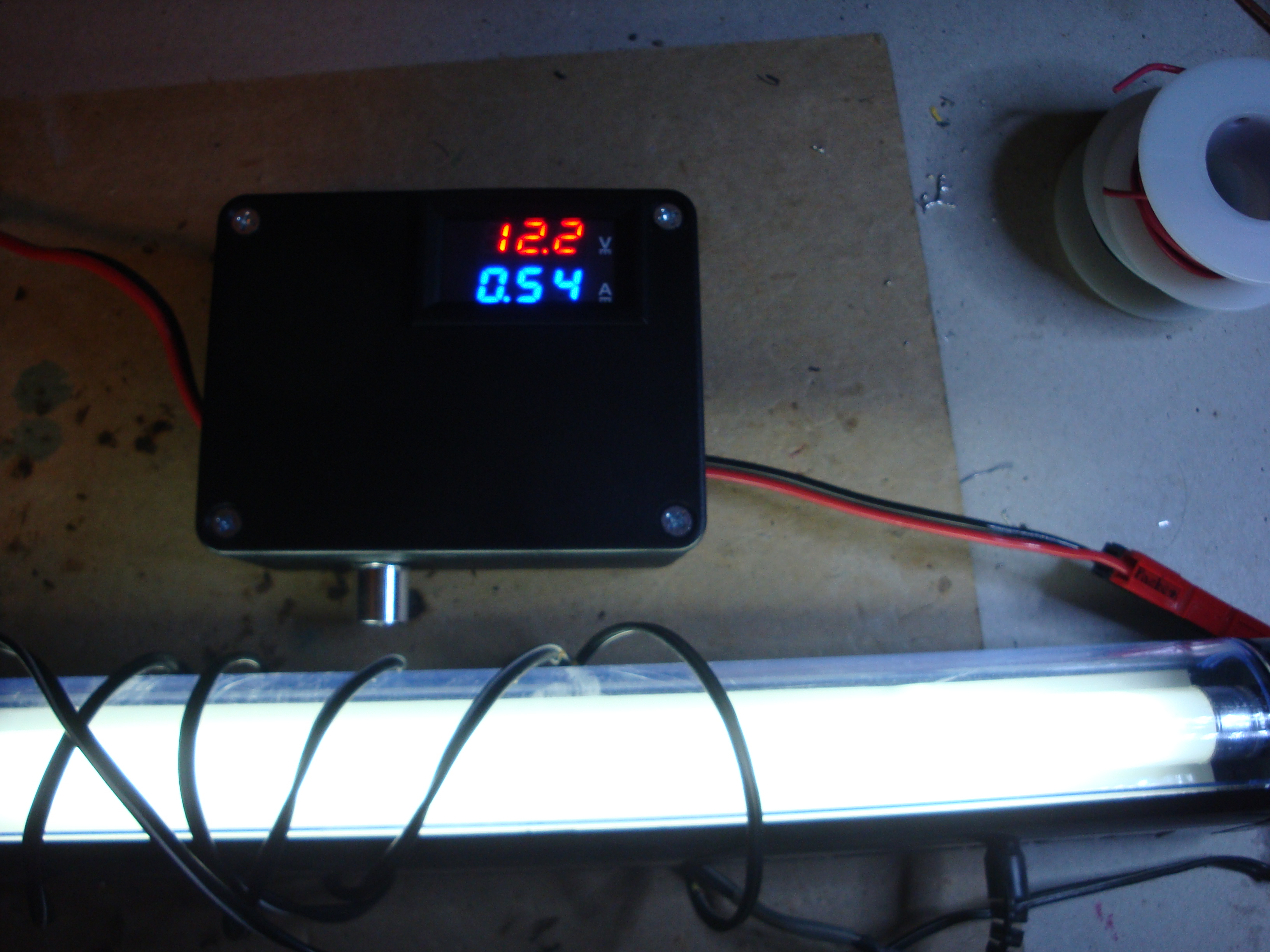
The next image is of the box under test supplying power to a fluorescent lamp before I applied the labels.
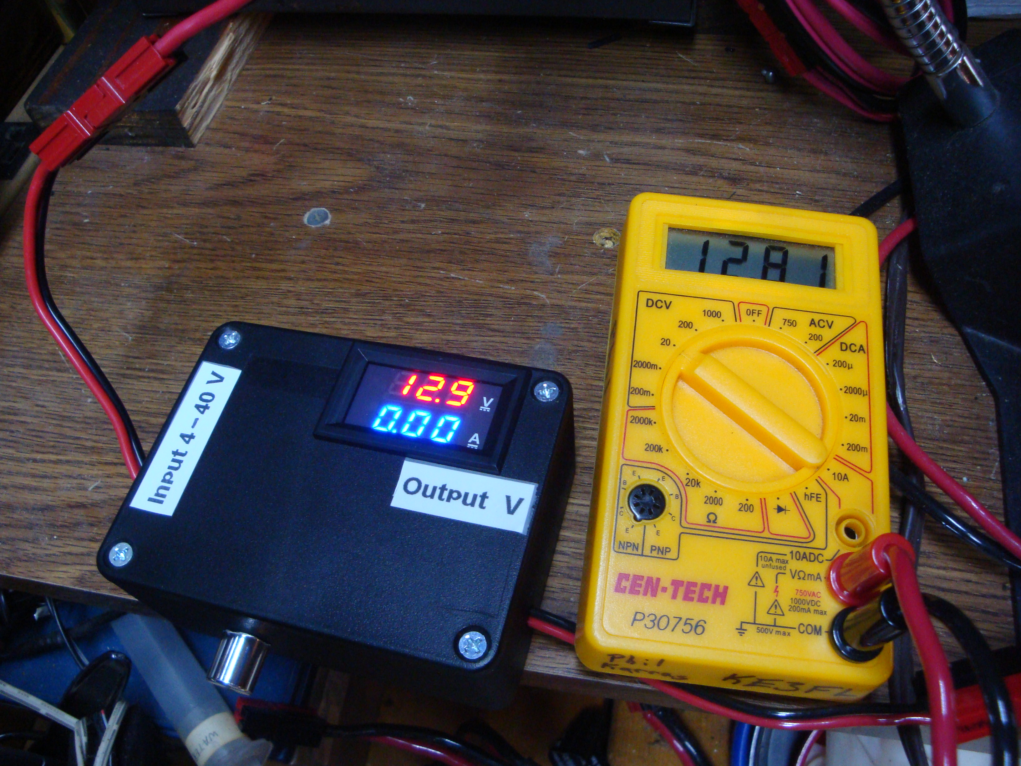
The converter box can be seen in the LAST image connected to the Astron SR-20A supply, set to 12.9V output and sporting the lables and compared to another Voltmeter.
If you have any comments or questions please use the link below to contact me. Remember to check your email address as entered since you won't receive an answer if it is wrong. If you do not receive a reply within 24 hours try again, the email address you entered may have been wrong. If I don't reply quickly after the second attempt I may be out of email contact and I'll get back to you as soon as I can.
Phil Karras, KE3FL
Questions, Comments? Send me an email (Please include what page you were on. This is the "Adjustable Add-On Power Supply" page.)
 Return to:
previous page
Return to:
[My Home page]
Return to:
previous page
Return to:
[My Home page]
With this in mind I went web diving to search for adjustable power supplies and I came across the following description: “DC 4V-40V to 1.25-36V Buck Converter 200W 8A Module” which I thought would change any input voltage from 4V to 40V into any output voltage from 1.25V to 36V. So I thought WOW I could change 13.8V into anything from 1.25 to 36V up to 8Amps (assuming the input power supply could supply the needed power (V*A). So, the Astron 13.8V 20A supply is up to 276 Watts, and that would mean ~ 24V up to 10Amps, well only 8 because a few things like losses and the module only claims 200W and a max of only 8A.
Unfortunately I got it wrong, a buck converter is only able to adjust the voltage up to a max of the supplied input voltage, or less. It does NOT buck the voltage up higher than the supplied input voltage.
If you want to find a buck converter try searching on, “Buck Converter 200W 8A Module” or leave off the power/amp limits and you’ll find versions up to 12A.
I then found and bought a few Volt & Amp displays. The ones I bought required a minimum of 4 Volts to operate. I wanted to see down to the lowest Voltage so I built a 9V 100 mA supply using a small 7809 regulator. If you want to find the displays on eBay try searching on, “Digital LED DC Voltage/Current Display/Meter” See the image …

I wanted to be able to replace any of the parts/boards so I modified a few things to allow all wires coming in to be either screwed or clamped to other wires or boards.

I added the output wires and the display with a clamp soldered to the display’s positive current wire. The display was attached to the top cover.
Pleas note that the wiring I used is different from that originally tried. The black wire from the display no longer returns to the power source. I noticed a ground-loop problem when I attached this wire to the 9V supply return. When I cut it the current and Voltage read much closer to the actual values. When it was connected the current was reading 70% too high!
The next image is of the box under test supplying power to a fluorescent lamp before I applied the labels.
The converter box can be seen in the LAST image connected to the Astron SR-20A supply, set to 12.9V output and sporting the lables and compared to another Voltmeter.
If you have any comments or questions please use the link below to contact me. Remember to check your email address as entered since you won't receive an answer if it is wrong. If you do not receive a reply within 24 hours try again, the email address you entered may have been wrong. If I don't reply quickly after the second attempt I may be out of email contact and I'll get back to you as soon as I can.
Phil Karras, KE3FL
Questions, Comments? Send me an email (Please include what page you were on. This is the "Adjustable Add-On Power Supply" page.)
Return to:
previous page
Return to:
[My Home page]