Center-Tapped Joule Thief Plus
Started: 9/15/2019 - Last update: 01/15/2020
I read about a center-tapped joule thief and decided I might be able to use
this as a better voltage booster circuit. Unfortunately, it did not seem to
work as well as I had hoped.
The basic idea is that, with a center tap there are two outputs of opposite polarity and these can be used to "double" the available power into a capacitor to be used by a low-current circuit needing a higher voltage.
In playing with this circuit, I didn't feel it really had any advantages over the basic joule thief circuit in supplying a steady voltage to even an LED unless the LED was a simple 20 mA LED.
I wanted to use this circuit to drive a flickering amber LED for more realistic Christmas Window Candles. The voltage dropped to around 2.0 - 2.2 Volts and, while the flickering LED worked, it seemed dimmer than I wanted.
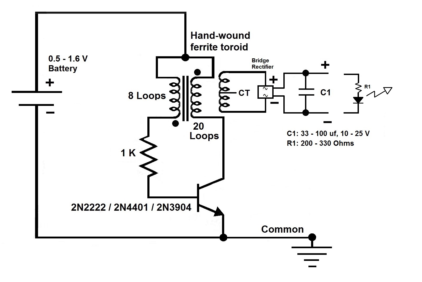
The schematic shows the initial center tap. Initially I used 20 loops of wire, so ten on each side.
NOTE: Thanks to Dean who caught the fact that I previously had the transistor collector shorted to ground which is NOT the way this circuit was designed. I had simply removed the LED that was there for the standard Joule Thief circuit.
The below trace shows that the positive and negative pulses happen at the same time and are about the same value, as expected. This leads to a problem: there is no second pulse coming during the off-time of the first. This gives a short duration pulse and then a longer down time. In other words there is no negative going pulse to keep the voltage even.
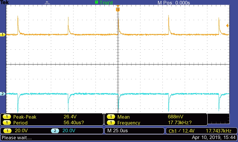 Trace 1: center tap trace
In thinking about this I was wondering what would happen if the center tap was ignored. I measured the output from the extra loops of wire end to end. The trace below is for the 22 loop version.
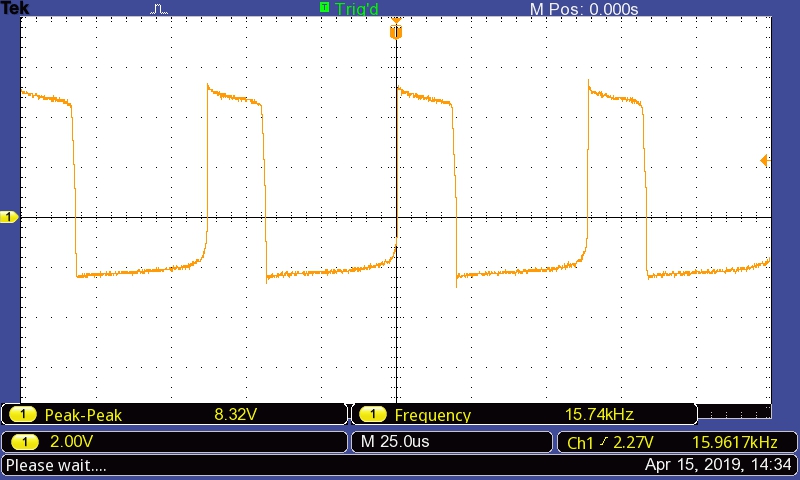 Trace 2: End-to-end coil of extra wire, 22 loops
In this trace it can be seen that there are two pulses: a large positive pulse and a smaller, lower-voltage, negative pulse during the off-time of the positive pulse. I liked this better, even though the negative pulse is only about 2+ Volts. That is better than no Volts with the center-tapped version.
Using a full wave bridge rectifier now gives around 2.4 - 2.5 Volts to drive the flickering LED. This worked much better and the LED was noticeably brighter.
I did notice a problem when using a capacitor with this circuit: If the LED is not attache and the circuit is powered up, the voltage on the cap will be as high as the voltage-boosting circuit. I believe this can be in the 30 volt range, the peak to peak was closer to 60 Volts. See Trace 3.
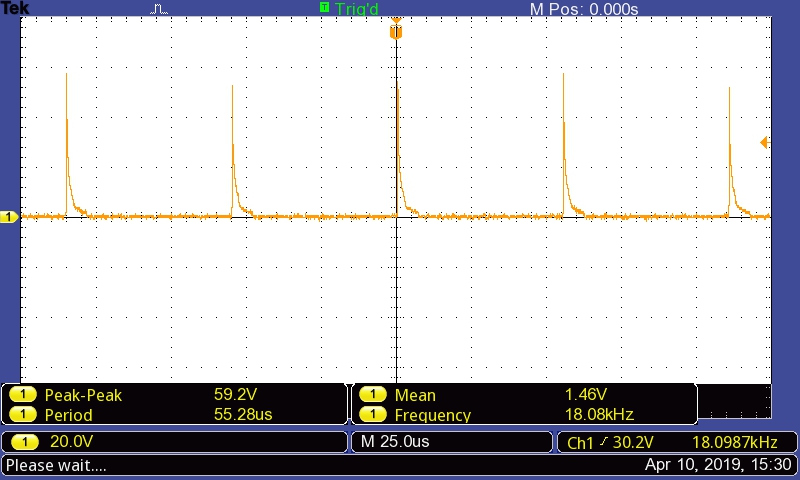 Trace 3: Free wheeling voltage boosting circuit, Left side
If the LED is then connected to the circuit, it dies almost instantly, whether the circuit is energized or not, unless one shorts out the capacitor, thus lowering the voltage stored there. This being the case, I decided it might be prudent to use a 330 Ohm resistor to help reduce the current going to the flickering amber LED.
When this was done and the voltage across the capacitor was measured, the voltage was found to be 4.0 Volts. If the voltage is 4.0 Volts, then a resistor of ~ 200 Ohms should be sufficient to supply the LED with ~ 20 mA of current. I used a 330 Ohm resistor. Since it worked fine, I left it in.
In the schematic I have just a resistor LED combination, but this was replaced with the flickering amber LED with its circuit, either internal to the LED or an external circuit with an amber LED attached. Whatever I found in the batch of dead flickering candles we had. (They were "dead" because of dead 2032 batteries, and I wanted to run them from this circuit using dead AA or AAA batteries.)
Phil Karras, KE3FL
Questions, Comments? Send me an email (Please include what page you were on. This is the "Center-Tapped Joule Thief Plus" page.)
 Return to:
previous page
Return to:
[My Home page]
Return to:
previous page
Return to:
[My Home page]
The basic idea is that, with a center tap there are two outputs of opposite polarity and these can be used to "double" the available power into a capacitor to be used by a low-current circuit needing a higher voltage.
In playing with this circuit, I didn't feel it really had any advantages over the basic joule thief circuit in supplying a steady voltage to even an LED unless the LED was a simple 20 mA LED.
I wanted to use this circuit to drive a flickering amber LED for more realistic Christmas Window Candles. The voltage dropped to around 2.0 - 2.2 Volts and, while the flickering LED worked, it seemed dimmer than I wanted.
The schematic shows the initial center tap. Initially I used 20 loops of wire, so ten on each side.

NOTE: Thanks to Dean who caught the fact that I previously had the transistor collector shorted to ground which is NOT the way this circuit was designed. I had simply removed the LED that was there for the standard Joule Thief circuit.
The below trace shows that the positive and negative pulses happen at the same time and are about the same value, as expected. This leads to a problem: there is no second pulse coming during the off-time of the first. This gives a short duration pulse and then a longer down time. In other words there is no negative going pulse to keep the voltage even.
Trace 1: center tap trace
In thinking about this I was wondering what would happen if the center tap was ignored. I measured the output from the extra loops of wire end to end. The trace below is for the 22 loop version.
Trace 2: End-to-end coil of extra wire, 22 loops
In this trace it can be seen that there are two pulses: a large positive pulse and a smaller, lower-voltage, negative pulse during the off-time of the positive pulse. I liked this better, even though the negative pulse is only about 2+ Volts. That is better than no Volts with the center-tapped version.
Using a full wave bridge rectifier now gives around 2.4 - 2.5 Volts to drive the flickering LED. This worked much better and the LED was noticeably brighter.
I did notice a problem when using a capacitor with this circuit: If the LED is not attache and the circuit is powered up, the voltage on the cap will be as high as the voltage-boosting circuit. I believe this can be in the 30 volt range, the peak to peak was closer to 60 Volts. See Trace 3.
Trace 3: Free wheeling voltage boosting circuit, Left side
If the LED is then connected to the circuit, it dies almost instantly, whether the circuit is energized or not, unless one shorts out the capacitor, thus lowering the voltage stored there. This being the case, I decided it might be prudent to use a 330 Ohm resistor to help reduce the current going to the flickering amber LED.
When this was done and the voltage across the capacitor was measured, the voltage was found to be 4.0 Volts. If the voltage is 4.0 Volts, then a resistor of ~ 200 Ohms should be sufficient to supply the LED with ~ 20 mA of current. I used a 330 Ohm resistor. Since it worked fine, I left it in.
In the schematic I have just a resistor LED combination, but this was replaced with the flickering amber LED with its circuit, either internal to the LED or an external circuit with an amber LED attached. Whatever I found in the batch of dead flickering candles we had. (They were "dead" because of dead 2032 batteries, and I wanted to run them from this circuit using dead AA or AAA batteries.)
Phil Karras, KE3FL
Questions, Comments? Send me an email (Please include what page you were on. This is the "Center-Tapped Joule Thief Plus" page.)
Return to:
previous page
Return to:
[My Home page]