Li Battery Voltage Boosting Circuit for 4 LEDs
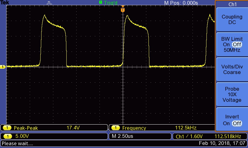
Image 1:
Basic circuit using a 5.1 KΩ Base resisitor
The basic circuit used the standard best loops ration 8 by 20 loops on the
toroid and was powered by a Li 18650 battery starting at ~ 4.2V.
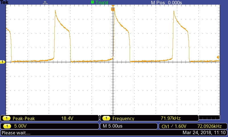
Image 2:
Rebuilt circuit using a 5.1 KΩ Base resisitor
The rebuilt circuit used the same 8 by 20 turns on the toroid but instead of
using a Li battery starting at ~ 4.2V it was using a DC power supply of about
3.76V.
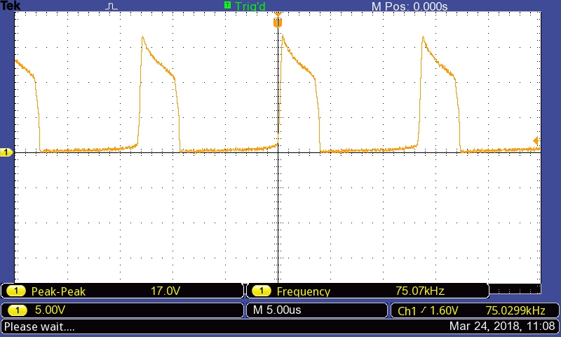
Image 3:
Rebuilt circuit using a 10 KΩ Base resisitor
The peak voltage when using a 10 KΩ resistor was observed to be anything
from 16.6 to 17.2 Volts.
The rebuilt circuit, using either resistor, shows a slightly longer off time
to the on time. The original "basic" circuit showed an on/off time ratio of 1
to 2, the rebuilt circuit shows the ratio as 1 to 2.5 so approximately 25%
more off time. I think this is beacuse for the "basic" version I used a
pre-wound toroid I had in the drawer so I don't know the loop ratio for that
version but for the "rebuilt" version I know I used the best ratio of 8 to 20
loops.
On the other hand, the difference may simply be that I tested the "basic"
version using 4.2V and the "rebuilt" version using ~3.75V since the power
supply to be used for this circuit was known to be running at 3.76V.
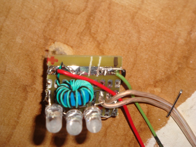
Image 4:
Circuit board Above View
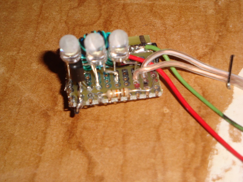
Image 4:
Circuit board Below View
Questions, Comments? Send me an email
(Please include which page you were on. This is the
Beyond the Simple Joule Thief page.)
 Return to:
previous page
Return to:
[My Home page]
Return to:
previous page
Return to:
[My Home page]