The Simple LED TesterI've seen LED testers in a number of different catalogs but could never buy one since it's so easy to test an LED with a resistor and a 5-Volt supply. On the other hand, I never wanted to build one where I'd have to use a number of batteries. After playing with the Joule Thief, I decided that here was a circuit that would be a good LED tester and it only needed one battery, and a "dead" one at that. The criteria I used was the following:
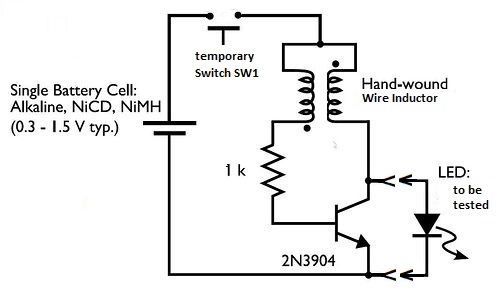
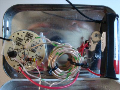
So the circuit was the typical Joule Thief circuit with two changes: first a temporary on-switch was placed from the positive terminal of the battery to the input (twisted pair of wires) of the inductor. Second, the LED was replaced with a socket to allow any LED to be tested. The circuit is not powered until the button is pressed and that shouldn't be done until an LED is in the circuit. I used a salvaged circuit card from a dead LED light bulb. It only had two resistors, three capacitors, and four diodes on it so I removed all of those and found that the card had plenty of connecting pads to hold all the parts I needed to use.
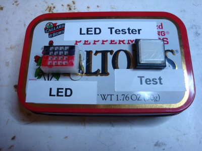
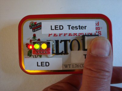
Since nothing was critical, I didn't bother being neat about the circuit and how it went into the Altoids tin either. You can see the finished circuit inside the tin in Photo 1 above. The closed-up and labeled tester with the LED not plugged in, and then plugged in and being tested, is in Photos 2 and 3.
An interesting observation is that if the LED is put into the socket backwards so that it won't light up when the button is pressed, the LED will dimly flash when the button is released. This indicates that the LED is probably good and in backwards. Switch the LED around and try again. Try this even if you do not see the flash; you may simply have missed it or, in the case of standard LEDs, it may not flash when inserted backwards. This flashing may only apply to the ultra bright LEDs. If you've tested the tester with a known, good LED and it lights up, and if the LED under test doesn't light up in either orientation, then the LED is bad. Throw it out. You do NOT want it in your junk box. This is a simple circuit to build and, even with the drilling and gluing, it only took me an hour from start to finish. Phil Karras 02/19/2014 I also made a replacement Piano Light "bulb" out of two LED modules with three LEDs in each of them, the base of a dead LED light bulb, and the circuit from inside a 12V, 500mA switching power supply. Another item made with a home made power supply is the, 5 LED Night Light.  Return to:
previous page
Return to:
[My Home page]
Return to:
previous page
Return to:
[My Home page]
|