Reusing that Wall Wart, Revisited
|
HamCalc SIDEBAR:
The HAMCALC Method using the Wall Wart Rating Calculator Program
To use the HAMCALC Wall Wart program you need only a voltmeter
and two load test resistors, then respond to the program prompts
as follows:
Prompt 1: "ENTER: Current rating on the Wall Wart label (mA) ?"
Prompt 2. "ENTER: Measured No-Load voltage ?" At this point the program halts to give you the option of continuing or linking to other Hamcalc programs that calculate how to combine standard value resistors to obtain the required load resistor values.
Prompt 3. "ENTER: Actual resistance of load resistor #1 ?"
Prompt 4: "ENTER: Voltage across (this) resistor ?"
Prompt 5. "ENTER: Actual resistance of load resistor #2 ?"
Prompt 6: "ENTER: Voltage across (this) resistor ?" The screen will display a table showing the calculated rated voltage, current, watts, and load resistance at each of eleven equally spaced currents from zero to about twice the current rating shown on the wall wart label.
Prompt 7: "Want a specific load in (v)olts,(m)illiamps,(o)hms, or
just (q)uit ?"
Prompt 8a:"ENTER: Voltage ?" The program repeats prompt 7. You may recalculate new values as many times as you wish, until you quit the program in Prompt 7.
by George Murphy, VE3ERP |
My first article on this subject was published in World Radio, October 2000, page 24, and in QRP Quarterly, July 2000. In that article I tried to give some ideas on how to decide to either reuse the Wall Wart as it is, or not. I published the curve and equation for the one unit I tested. George Murphy VE3ERP (of HamCalc fame) saw it and we collaborated to get a generic form of the equation into HamCalc, Version 48 or higher. (see the sidebar and footnote on HamCalc.)
This article will expand on the first article. I will show how George’s program works and how we can use it to make the decision to either reuse the Wall Wart as it is or use it with a voltage regulator. I have also cleaned up the two graphics of the first article, added more examples, and added HamCalc data to the graphs to show how well HamCalc does. I have added two more cases with different WWs along with the HamCalc data.
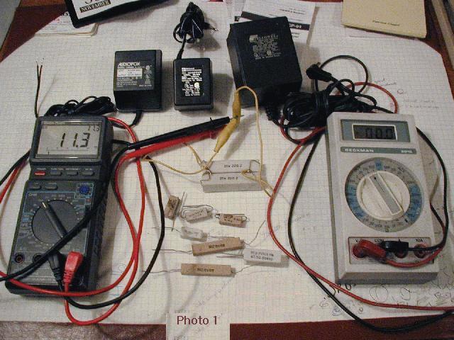
I used three different wall warts, two multimeters and a number of different resistors to make these tests. The devices used for these tests and the test circuit can be seen below in Photo 1 and Schematic 1.
What is a "wall wart"? I'm sure you have a number of these things around; I sure do. These are those little (or not so little) black (but sometimes white) cubes with AC power connector blades on one face. You plug it into the wall and it converts the AC voltage to DC voltage at some specified current. Once you plug it into the AC outlet, it sits there like a black (or white) wart on your wall, thus the term of endearment, "wall wart."
If you're like me, you simply can’t throw these things away if they still work, even when the item they came with and powered is long gone. I have all sorts of wall warts (WWs), from 9 volts to 15 volts, and with different current ratings.
There are a few things you need to know if you want to reuse a WW to power a different device; they are:
1. You have to have the right power plug to fit the new device.
2. The plug must be wired correctly; this is called the right "polarity." Your new device won't last very long if you apply positive voltage to the negative connection. Most devices are still center positive but more and more are center negative. (I hate center negative. It puts the positive voltage on that long outer barrel and cars are usually chassis negative. A good way to short things out in the car!)
4. You need to make sure there is sufficient current.
3. You need to supply the correct voltage with no more than +10% voltage at the lowest current the device uses.
Let me say that the voltage + 10% "rule" is not a real rule. In general, most devices that are battery powered can handle a voltage of at least 10% higher. This is because most transistors and Analog ICs are designed to work within a range of voltages. The digital ICs used today can also run on a range of voltages or there is an internal voltage regulator in the design if they cannot. The big problem comes from electrolytic capacitors, which may be rated at close to the operating voltage of the device. The best thing to do is go through the user’s manual to find out just how much of a voltage increase the device can handle. If you cannot find anything listed, either go to the internet and ask or open up the device. In my HF/AM/FM receiver I found that the caps were rated for 12 volts and the radio operated on 9 volts. I was able to operate it from 7 to 11 volts without any problems encountered. I don’t recommend running anything at more than 10% above its rated voltage unless the manufacturer says it’s OK. (I have an HT that can operate on anything from 6 to 14 volts.)
While we all know that the first two points above are very important, some of us may not understand the importance of the last two taken together when using a WW. This is because we've been taught that if a supply has the correct voltage and a higher-than-needed current rating (like a battery) everything will be fine. After all, the device only takes as much current as needed. The power supply does not "force feed" the device with more current than it should.
For a regulated constant voltage power supply, this attitude is just fine, but for the unregulated fluctuating voltage WW, it is not. The two numbers given on the WW must be taken together! Perhaps a graph will help here.
Here is the Voltage vs Current graph for a 12 Volt, 300 mA wall wart. This is the kind I’ve used for my Trickle Charger Plus. (See
http://www.qsl.net/ke3fl - and page down to: "Other KE3FL Articles, QRP et al:" - for more details on the Trickle Charger Plus.)
We can see that the lower the current draw from the WW, the higher the voltage. On this system, if we take only 10% of the rated current, we get a voltage of about 15 volts, which is 25% higher than needed. So, unless the manufacturer of our 12V device says 15 volts is OK during standby operations where the device only uses 30mA, we’d better not use this WW for this application.
The form of the equation for this curve is:
Y=a[0]+(a[1]+(a[2]*X))*X
where:
Or the equation can be written as:
V = 16.21 - .01642*I + 8.582E-6*I^2
where:
Y is the same as V in volts, and
X is the same as I in mA.
NOTE: I've used four digits in the equation but my
measurements used 3 digits at times. Thus, the final answer should
be limited to three digits.
The equation was derived using a curve-fitting program I wrote sometime
around 1990. I tried both a 2nd and 3rd order polynomial curve fit.
While the 3rd order polynomial does give be a bit better fit I have
rejected it, for the present, because a 2nd order equation is easier to
use and is close enough. Here is the third order curve fit and the
equation for comparison, see Graph 01:
Here:
V = 16.44 - 2.402E-2 * I + 3.800E-5 * I^2 - 2.753E-8 I^3
While the third order curve is better for all wall warts, the 2nd order
equation is easier to approximate with George's method and it takes
fewer measurements. My last reason for using the 2nd order equation and
approximation is that it is close enough, at least confirmed with
these three units.
So, let's continue with a design example, let’s assume you have a radio that needs 12 Volts at up to 400 mA. We have tested the radio and it works all the way down to 9.5 volts just fine. The lowest current the radio uses (radio on but volume all the way down) is 200 mA. We have a WW rated at 12 V 300 mA and we want to know if this WW will be able to power our new radio. At 200 mA, our WW will be up to a voltage of about 12.9. This is below the 13.2V or the +10% voltage so that looks OK. Now at 400 mA, the voltage will be around 11.0, which is well within the operating limits of the radio, so it looks like this WW will be OK for the new radio.
Now let’s take a look at how HamCalc does as seen in Graph 02. This is the same curve as seen in Graph 1 but now plotted with the HamCalc points included (NOTE: All curves are generated based on the measured data points only):
The HamCalc table that gave me the points can be seen in Screen 1:
The HamCalc plot shows us that at 200mA we are at around 13.5V, doing the calculation using HamCalc and entering 200 (for the milliamps, ma) gives: 13.7 (Volts), both of which are just a bit above the 10% rule I use, but not so much that I’d worry about it yet. At the high end we see that at 400mA the voltage will be about 11.5 (11.6) volts. Still good. So a quick check using HamCalc shows that this WW might be OK to use. The advantage here is that we only need to make three measurements to supply HamCalc with its needed inputs and they don't have to have anything to do with the device we want to power with the WW. The last measurement can actually be made with the device. Set it up so you can measure the voltage during its low current need. Start the radio at a high volume so it needs 400mA and the WW will supply around 11V. Then, lower the volume until you get to a voltage of 13.2 or 200mA, whichever comes first. If you reach the lowest volume and the voltage is not higher than 13.2V, then it should be safe to use this WW for this application.
I suggest that you first measure or read about the current requirement for the new radio. Then find a WW that supplies the needed current at the needed voltage with no more than a +10% higher voltage. It must still have an acceptable low voltage at full current use as well. HamCalc makes the test possible without having to resort to more tests with resistors. We see here that we are close - this WW might just work and since it is safe at the high current/lowest voltage point, we start there and work our way down to the low current/highest voltage point.
Another way to supply power is to get a WW that exceeds the needed voltage and current. The voltage in this case should be at least 2 volts above the voltage needed, with current rating above that needed as well. We now use a voltage regulator-either the 78xx series or the LM317 adjustable variety. Make sure you use a regulator that can supply 50 to 100% more current than the needed device and that you heat-sink it properly. I did something like this for my new/used HF receiver. I used, inside the receiver, the 9 volt regulator and then supplied it, through the external power port, with 12 volts from a battery being trickle charged. This way, if the power fails the battery takes over.
Let’s look at another WW to see if it can handle an HT. This HT can run on anything from 7 to 13.8 volts. When using 13.8 volts and transmitting it requires 1.2A. When it is silent and monitoring it only requires 30mA. I have a WW rated at 15V and 1.4A-will that do? Well, if the WW really is 15V at 1.4A, it will be at a higher voltage when suppling 1.2A, so I would say no, not directly useable. However, let’s check it out with HamCalc anyway. Graph 03 shows the following:
HamCalc shows that at about 1.2A, the voltage will be around 14.7V (calculated: 14.3), a bit too high. Of course, at 30mA the voltage is way too high around 18.7V (calculated: 18.5). However, this points out that with a regulator set for 12V, we should be able to do what we want. The LM317 needs at least a 2V higher supply than required for the application and we see that this WW can supply that, even though it doesn’t look like it is still meeting manufacturer’s specification. (Notice that at 1.4A, the voltage is a bit below 14V not 15 volts, as measured and calculated by HamCalc.)
Below (in Circuits 1) are typical circuits. You can use either a small 7809 to power a small device that normally uses a 9V battery, or an LM317 to make a 13.8V/3A supply for a typical HT. For the 9V version, you can use the lower capacitance values; for the LM317 or LM350, use the larger values:
NOTE: R2 for the LM317/350 can be a variable resistor, which makes it a variable Vout.
The LM 317 can supply up to three amps, the 350 up to five. The equation for the resistor divider for the LM 317, 350 is: Vout = 1.25(1+R2/R1) + (Iadj)(R2). Since Iadj is about 50 uA, this term can be left off in most cases. There will be some slight increase in Vout with insufficient load.
By the way, HamCalc also has an LM317 power supply design program, so you don't have to do the math here-just use this program to do it for you.
As a last example, I have a small watt meter that requires a 9V battery and I have a 9V 200mA WW. Will it be able to substitute for the battery? Well, 9V batteries normally only supply around 9mA, and for my wattmeter I measure it using 3 to 6 mA. The curve I measured for this WW looks like (Graph 04) (with the HamCalc points shown):
This WW looks really bad! About the only time it gives 9V is
under a no-load condition. However, we don't need much, only 3 to 6
mA, so perhaps this one will be fine. Using the curve, we see we're
very close to being OK. With HamCalc we compute 9.08V at 3mA and
about 9.04 at 6mA, so we can use this WW just as it is for this
application.
Most 9V applications can run the battery down to about 7V and
still be operational. How much current can this WW supply at 7V?
The graph show this to be around 140mA, HamCalc says: 152mA.
So we could probably still use this WW even if the device to be
powered needed about 140 to 150mA. Still, it is obvious that this WW
no longer meets the design specifications of 9V at 200mA!
I hope this helps you understand what can and cannot (or should not) be done with a WW from some other defunct device for your new device. While these are wonderful little devices, we must know how to use them properly or we'll end up destroying the battery we're trying to charge or the device we're trying to power.
I've used them for my "Trickle Charger Plus" to keep Gel Cells,
NiCds, and Lead Acid batteries topped off and "Emergency Ready" for
years.
I've also used them as they come, to power CD players,
radios, and tape players. Last, I've used the regulated versions to
power electronic games, CB radios, FRS HTs, and 2-meter HTs.
73 de KE3FL
Phil Karras
AEC Carroll County MD
ORS, OES, & VE
ke3fl@arrl.net
HAMCALC for Windows or MS-DOS
HAMCALC 48 was the first version that contained the needed software for
calculating the reuse of a Wall Wart (wall transformer power supply.)
Presently (02/07/2011) HAMCALC is up to version 129. |