TRICKLE CHARGING, by Phil/KE3FL
Return to KE3FL WebPage
Return to: Power Sources
Return to: For Sale or Swap Page
New Kit Building Instructions
Go to:
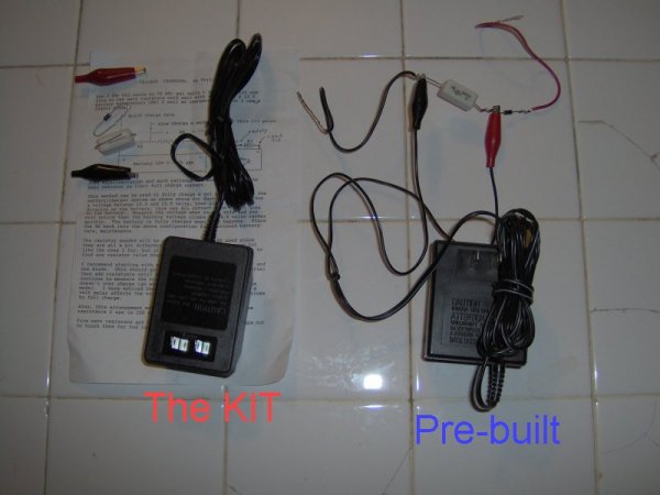
order the Trickle Charger kit, or pre-built
CHARGERS
There are basically two types of trickle chargers, the first uses
electronics to insure that the trickle rate is "forced" into the battery
and the second ends up suppling the trickle rate by design.
BATTERIES
The two basic types of rechargeable batteries, NiCd and lead acid, lead
acid includes gel cells, both can be charged by the tenth rate method;
that is, 1/10th the full power rating is used to charge the battery for
10 to 12 hours. If we have a 600 maHr battery, we would charge it at
60 ma for 10 to 12 hours. If we had a 60 AHr battery we would charge it
at 6 amps for 10 to 12 hours. Needless to say, most lead acid charges
are of the "dump-as-much-as-you-can-as-fast-as-you-can" variety. This
type of charging is ok for liquid lead acid batteries but not for NiCds
or for Gel Cells. While Gel Cells can handle much more recharge current
than NiCds they can not handle as much as liquid lead acid.
TRICKLE CHARGERS
What I want to describe now is the inexpensive trickle charger I have
designed. This came about from the fact that a normal lead acid
battery charger starts off at six to 10 amps and as the battery becomes
charged falls down to the one amp range. This is a perfectly
acceptable charging method for lead acid batteries, even gel cells (as
long as the maximum current can be handled by the gel cell.)
The idea of a trickle charger is that it can be left charging the
battery continuously without fear of damage to the battery. To do
this, the rate must be no more than 1/100th the power rating of the
cell, and at least as high as the internal discharge rate of the cell.
Most NiCd batteries will self discharge in about 3 months, or about 90
days. This means that the self discharge rate is about one percent per
day, so we see that the "rule-of-thumb" 1/100th trickle charge rate was
designed to offset the self discharge rate of NiCd batteries. This
rule is used for all rechargeable batteries that I am familiar with.
(I am not yet familiar with the newer rechargeable Alkaline batteries.)
So, we need to design a recharger that can supply no more than 1/100th
the current rating of the battery we wish to trickle charge. An
important point is that neither liquid or gel cell lead acid batteries
have this high a self discharge rate, and in fact some well designed
NiCds don't either.
MY DESIGN
As I described before, a trickle charger can be of two types, one that
always supplies the trickle rate of current, or the one that starts
higher but ends up at the trickle rate. The design and electronics for
the continuous trickle charger is more involved and more expensive and
require transformers of much higher voltages. The less expensive way
is to design around a transformer that will supply the correct
voltage/current required to be a trickle charger after the battery is
fully charged.
I have to admit that I simply stumbled upon my current supply of
transformers and they turned out to be just about perfect for trickle
charging lead acid batteries. The transformer is rated at 23VAC center
tapped at 400 ma. Center tap gives us 11.5VAC at 400 ma. Remembering
that the difference between RMS and Peak AC-voltage is: Peak = 1.414 *
RMS gives about 16 VDC. A lead acid battery needs about 13.8 to 14
volts to charge fully. As it turns out, the little transformer with
two diodes and a 25-30 ohm 5W resistor will supply about 375ma to a
discharged battery, and about 40ma to a charged battery. This would be
perfect for a four AHr NiCd, and experience shows that it works well
for lead acid gel cell of 25 AHr or a liquid lead acid of the 70 to 80
AHr range as well as a 7 AHr gel cell. The unit I built was suppling
40 ma to each of these batteries when they reached the 13.1 volt range.
BUILDING THE TRICKLE CHARGER
NOTE: All WallWarts I now supply are rated: 12V @ 300mA DC so you will
not need to open the case or install any
diodes or resistors. You will still need to install the clips (supplied)
(or a plug - not supplied) on the wires. Be sure to measure the output
and mark down which wire is positive and which is negative. The red
clip goes on the positive wire. see the
New Kit Building Instructions
Building the trickle charger is very simple. The most complicated part
is opening the transformer case (which you can skip if you want to put
the protection and diodes outside.) To open the case, squeeze one edge
at a time in a vice until the seam bulges. As the side bulges, use a
sharp knife to find an opening (or make one) and use the blade to
persuade the rest of the seam to open. You'll need to do this for the
three main seams. (I use my Swiss Army Knife.) It needs to be sharp to
start but we want to persuade, not cut, so use some prying force (twist
the blade). If you hear a loud POP, don't be too surprised; this is the
seam giving way all at once and is, in fact, the best way for it to open.
I use a knife to start the process and a screwdriver to finish it. It
can be finished outside of the vise.
Once the three seams are open, use brute strength to pull open the case
completely. It should not take much.
Cut the three wires that come to the outside at a point inside the case
that leaves enough wire on each end for stripping and soldering.
Solder a diode to the red and black wires that come from the
transformer so that the cathode (the pointed or banded end) of each
diode is free. These are each one-half of the positive supply and will
be attached to the red wire going to the outside. Use tape or shrink
tubing to protect these connections. Now solder the output ends (the
pointed ends) of the diodes together and then to the red wire that goes
to the outside. Again, use tape or shrink tubing to protect this
connection. Solder one end of the 25 ohm 5W resistor to the white wire
coming from the transformer and the other end to the black wire going
to the outside. These connections do NOT need to be protected since
there is nothing to short them if you protected the positive side
connections. Also, we want air to be able to flow around the resistor
with as little flow restriction as possible. The white wire going to
the outside has no connection, though you can solder it to the same
place as the black wire from the outside and make it a second negative
wire.
This is the minimal circuit needed for the charger. You can add a
small capacitor between the positive connection and the negative if you
want. If you do that, you should also add a one megaohm resistor
across the capacitor to help discharge it. These are not needed and I
do not recommend them.
MEASUREMENTS
Since the voltage is unfiltered alternating DC, the voltage will
measure low on your DC meter. Don't worry, this is normal. If you
simply add a capacitor to the end of the red and black wires, the
voltage will climb up to about 17 volts. (This is with no load and,
again, is normal.) Once you have checked this out and it all looks
okay, it's time to close the case and put connectors on the ends of the
red and black wires.
RESEALING
I used Methalene Chloride to seal the case together. This is a solvent
which just happens to melt the plastic of this case. Another solvent
which seems to work is the one used on plexiglass-type plastics. You
should be able to get that at any hardware store. Any good plastic glue
should also work. The big advantage of using a solvent is that it
doesn't add anything to the case to hold it together, and I know from
experience that the vise technique used before to open the case will work
again. Glue tends to add stuff to the situation and will need to be
cleaned off if you have to do it again and I don't know how easy it will
be to reopen the case.
THE HOOKUP
You will need to put a plug or clips on the outside ends of the red and
black wires so that they can be connected to the battery to be kept at
full charge. I use Radio Shack part #274-201, the two-pin male
connector I described in my ARES PLUG article. It is all right to use
the male connector in this case since we added the 25 ohm resistor.
This resistor insures the safety and life of the transformer should we
accidentally short out the red and black wires by limiting the current
to 375 ma, which is below the maximum continuous current of 400 ma.
NOTE: All WallWarts I now supply are rated: 12V @ 300mA DC so you will
not need to install any diodes or resistors
inside the case. You do still need to install the clips. Be sure to
measure the output and mark down which wire is positive and which is
negative. The red clip goes on the positive wire. see the
New Kit Building Instructions
SCHEMATIC
BASIC INFORMATION and THE HOOKUP
To charge a gel cell (12 volt version) it should be allowed to
go up to 14.4V. At that time it is considered (by the
manufacturers, 14.4 - 15 volts) to be fully charged. With a
battery eliminator type charger you may notice that the charge
current continues to drop as the voltage increases. This is a
good thing since you don't want to keep forcing 800 ma into your
battery when it is fully charged anyway.
Smart chargers measure the voltage & reduce the current so that
they keep the battery topped off continually after the battery
reaches full charge. If you measure the voltage at this time
you may notice it changing from time to time as the unit senses
that a bit more current is needed.
Another way to do the same thing is with a resistor/diode
accross the battery. Set the diode so that no current flows
through the resistor when attached to the battery. Then attach
a 12 V battery eliminator (one of which you no doubt have around
the house someplace) accross the resistor. In this way the
eliminator current is split between the battery and the
resistor. Pick the resistor such that its current draw is the
same from the eliminator as the battery's when the battery
reaches 13.8 Volts. With the diode this should be between 13.5
and 13.8 volts on the battery.
For 7 AHr Gel cells to 75 AHr gel cells I found that 125 ohm
five to ten watt resistors work well with the 300 ma @ 12 V
battery eliminators (BE) I sell as chargers. (For D1 I use a
1N4001 diode.)
Connections: Always connect the TCP negative wire to point 3. For
fatser charging connect the TCP positive wire to point 1. For
maintenance charging connect the TCP positive wire to point 2.
 Some experimentation and much patience are needed to find the
best resistor to limit the charge current correctly for a given
battery.
Some experimentation and much patience are needed to find the
best resistor to limit the charge current correctly for a given
battery.
This method can be used to fully charge a gel cell. I leave the
battery/charger system as shown above for days until it reaches
a voltage between 13.5 and 13.8 volts, then place the BE
directly on the battery, this way ALL current from the BE goes
to the battery. Measure the voltage when you do this and you
will notice that the battery voltage climbs to 14.4 volts rather
quickly. The battery is fully charged when this happens. Place
the BE back into the above configuration for continued battery
care, maintenance.
The resistor needed will be different for each BE used since
they are all a bit different, even the ones from the same lot
like the ones I buy, but if you buy a bunch you will be able to
find one resistor value that is good for the majority.
I recommend starting with a 100 ohm five or 10 watt resistor and
the diode. This should get you close (about 13.0 to 13.3 volts)
then add resistance until the battery is fully charged and
continue to measure the voltage for a few days to be sure it
doesn't over charge (go above 13.80 Volts when in maintenance
mode). I have noticed that in this arrangement even adding a
volt meter affects the voltage reading when the battery is close
to full charge.
Also, this arrangement works for lead acid batteries but the
resistance I use is 150 ohms.
Five watt resistors get HOT with the BE's I use so take care not
to touch them for too long a time.
Good-luck and I hope this helps. I am not finished with my
experiments but this is what I have found out so far.
73 de KE3FL/Phil
[Just the Hookup page]
To order a pre-built Trickle Charger Plus, send $15 plus $11 (05/2008) (1 lb) shipping via UPS
To order a kit please send $10 plus $11 (05/2008) (1 lb) shipping via UPS
to:
Circle Software
P.O. Box 74
Mt. Airy MD 21771
Make the check out to: Circle Software
Or, you can send me payment via
 ,
my account is:
,
my account is:

That's KE3FL but all lower case.
NOTE:
If you use a credit card on PayPal
please include an extra $1.00 for the PayPal fees, thanks.
(Don't forget to include contact and shipping information, thanks.)
Return to KE3FL WebPage
Return to: Power Sources
Return to: For Sale or Swap Page