|
What is meant by "beyond" the simple joule thief? Well, in this case it means two things:
First, the circuit used follows the 40% rule that I came up with in my experiments to improve the joule thief circuit. (See that article if you want to know what I mean by improve and how I came up with the 40% value.) Second, this circuit is designed for using a "dead" Li 18650 cell, not a dead AAA or AA 1.5 volt battery. The Li battery is not really dead in the sense of a dead none-rechargeable cell, but rather the Li cells I received claimed to be 9800mAh capacity but tested out as only ~ 555mAh. They work and do recharge at this level, but this is hardly a usable cell for a flashlight that on full brightness uses 550 - 700 mA. The flashlight would drain the battery in less than an hour of use. Even AAA alkaline batteries are better than 550mAh (usually about twice that.) The question is, what to do with these batteries? I did contact the seller, explained the situation, and eventually received a full refund. I hate to recycle things which are otherwise useable if I can only figure out what they can only be used for. In thinking about this, I came up with the idea that a joule thief circuit is simply a voltage-boosting circuit and, if it is used to increase the voltage of a dead 1.5V cell which is 0.5 - 1.0 Volts up to ~ 3.0 Volts to run an ultra bright white LED, why not use these "dead" Li 18650 cells to run 3 - 4 LEDs? Starting at 4.2 Volts and increasing the voltage to 12V would be a 3X increase, just as using a dead battery at 1.0V increased to 3.0V. I tried the basic better joule thief circuit to use a 4.2 - 3.0V Li cell. (See the above link about the 40% "rule" I came up with to make a better voltage-increasing circuit.) I figured that something in the circuit would have to change and worried about blowing up the NPN transistor. However, I simply decided to test it with the regular circuit components. When I did this, I soon discovered that the transistor over-heated so I increased the base resistor from 1KΩ to ~5KΩ. (I believe I found a 5.1 KΩ resistor in my resistor parts bins and used that.) See the modified circuit below. Note: You can click on the images below to see larger versions and for the scope image more detailed information. The scope larger image page has been updated as of: 03/25/2018 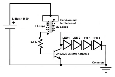
Schematic for the Li battery voltage boosting circuit 3.0 - 4.0V to 12 - 18V 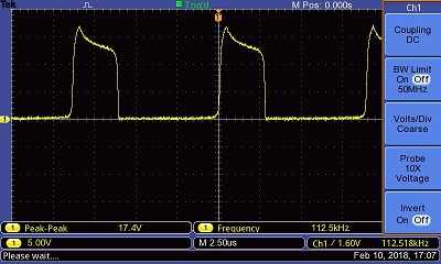
Li battery voltage booster circuit running 4 LEDs @ 17.4V Tests indicate that this circuit can run for ~ 10 hours before the battery reaches less than 3.0V when it needs to be recharged. Since it is a 555mAh cell, it doesn't take long to recharge these cells. I only did one test for 16 hrs and the battery was ~1.06 V when it ended. This is the one disadvantage of using a voltage-boosting circuit that can boost even 1.0V up enough to drive four 3V LEDs. Since a Li cell should not be discharged below 2.6V, this test may have ruined this cell. At this point, I would recommend that the night light be recharged every day if it has been left on all night. That should be before it gets below the 2.6 safe discharge voltage. The night/flashlight I put together used a reflector and circuit card salvaged from a dead 8 LED flashlight, a pill bottle as the battery holder, and a larger bottle that used to contain ground cinnamon, as the case. Last, an on-off switch. (I have micro on-off switches on order to replace the big switch presently in use.) 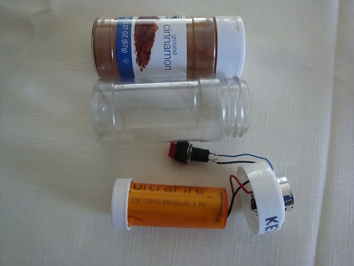
The cinnamon bottle and the battery holder bottle 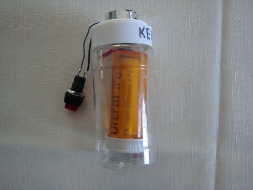
The battery holder bottle in the cinnamon bottle 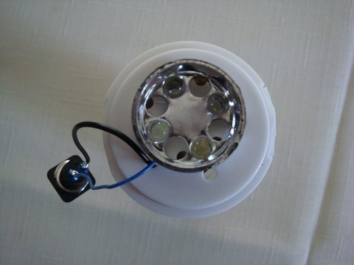
The salvaged flashlight reflector & four new leds 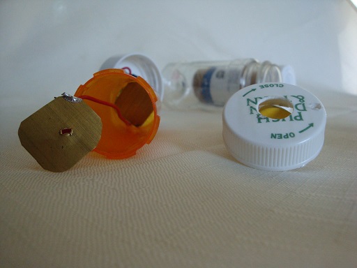
The battery holder/bottle connections 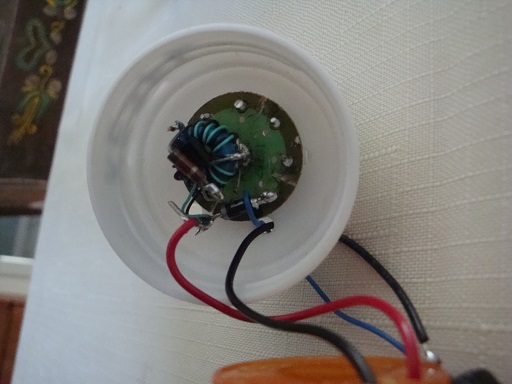
The circuit on the salvaged flashlight circuit board
In my case, I attached the diode to the common connection in the reversed direction so that the positive connections on the other end would not flow to the common connection. Also, the common connection has no positive voltage on it so nothing flows into the wires I connected on the other end. There are many good places to learn about diodes and here's one I liked from Spark Fun. From this link, you can see that I attached the anode to the common connection of the circuit and then attached the more positive wires to the cathode so no current would flow in either direction. The diode simply acts as an open circuit in this case, allowing me to tie down two floppy wires to a secure point so they don't flop around. This "dead" UltraFire 9800mAh battery was able to power the circuit and the LEDs were bright enough to help in the dark as a night light for 8 - 10 hours. At 12 hours, the battery was down to about 2.0 Volts, a bit too low for a safe, recoverable discharge for a good Li battery. Only time will tell what this will do to this bogus battery. |
