Joule Thief Information Page
Started: 1/20/2014 - Last update: 01/25/2020
|
Questions, Comments? Send me an email (Please include what page you were on. This is the "Joule Thief Information Page".)
I am not going to write about how to make a Joule Thief but rather I simply want
to add a little more information for everyone. As I come across more, I will
add it to this page.
So, what is a Joule Thief circuit? It is basiclly a voltage boosting circuit, at Wikipedia it is defined as, "A joule thief is a minimalist Armstrong self-oscillating voltage booster that is small, low-cost, and easy to build, typically used for driving small loads." A list of reference web articles/pages will be at the bottom of this page. After I got my joule theif working I did more research and some of my own experiments. The references below are some of the better articles I've come across which better explain how to build a joule thief as well as what you can expect duriung its operation. NOTE: While working on these tests I noticed that the voltages were lower than I expected. I located my oscilloscope calibrator and confirmed that the Tecktronix 453 scope was reading all voltages lower by a factor of 10. I have adjusted all measured voltages in the grids below to their correct values as of 09/03/2014. Yes, you guessed it, I was using a 10X probe. I'm glad I didn't pick up the 100X probe! 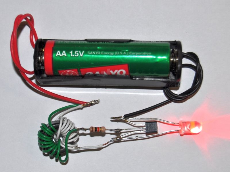
To read the wiki article, Click Here The above image shows the inductor wound with separate wires, but winding them with the two wires together is more efficient, faster, and easier to do: "if you wire in parallel so they interleave you can up the efficiency, sometimes by as much as 40% - mickeypop." Note: The comment passed on by mickypop was received on the Instructable, "Itty Bitty Joule Thief by Victor805" - see the link below. The next image shows how to do this for a simple joule thief where both wires are wound with the same number of turns. 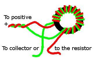
The above image is used with permission of Victor805 where it was used in his instructables: Itty Bitty Joule Thief by Victor805 and permission of Steve where the original was taken and modified by Victor. Steve's article on the joule thief is at: Joule thief - getting power from dead batteries * The first thing I want to show is a small table of the inductance values of the toroid bifilar inductor vs. the frequency of the pulses that I measured. NOTE: Some of the inductances will show 0/## this is because my inductance meter could not measure an inductance of only one winding. In these cases I also measured the inductance of the two windings.
All of the ferrite toroids were considerably different. It is rather interesting that I have an extremely small inductor at 616 μH, the OD of which is ~6mm and it is ~ 3mm tall, and the 223 μH inductor has an OD of 18mm and is 12mm tall. These are considerably different physically and very different inductances and yet the frequencies are very close. The red listing is, IMHO, where we want to be, if possible, even a lower frequency would be better still. I'd like to see if I can get it to ~ 500Hz! The reason for this is that the fewer the number of pulses per second, the longer the battery should last. Assuming all pulses are the same height/voltage and width/duration.
NOTE: The test for the 3851 core with a white LED was done on 11/27/2014 and it looks like I used a different white LED & 3904 transistor. The human eye cannot tell that something is pulsing when the pulsing is fast enough. Here in the USA we use AC current of 60 Hz and in Europe they use 50 Hz. So, if there was some advantage to it, and it could be done easily, getting the frequency down to 100Hz, would also be acceptable. You're probably thinking that we'd notice a difference in how bright the LED appeared. All I can say is that I didn't notice any difference between the LED going at 5KHz with the same LED going at 1MHz so I doubt we would notice any difference between 5KHz and 500 or even 100 Hz. I ran two tests - one using the 5KHz inductor and another using the 1MHz inductor - and there was a substantial difference in how long the 1.1V batteries lasted. I initially thought this was because the 1MHz inductor has 200 times more pulses per second. However, after thinking about it, I decided that it is only the percentage of time that the LED is on during one cycle that determines how much total energy is used and so determines how long the battery will last. Thinking about it a bit more, I thought almost the exact opposite, that it might be due to the length of time the inductor is "charging" that determines the life of the battery. The shorter the LED is off, the longer the battery will last. Or, put another way, the less current used, the more efficient the circuit is. I ran a few more tests on Feb. 22, 2014, and discovered that this looks correct. The longer the LED is off, the lower the frequency and the lower the amount of current is used by the circuit. All of this should mean that this is more efficient and should cause the battery to last longer. This does use more windings and so more wire. I believe that the items that determine the on vs total time are: the core, the wire size, the resistor value, and the LED. I'll have to run a few tests to see how each of these affects the ratio of LED on time to the time of one cycle. We get some indication that different inductances with the same core and the same wire do not change the on-time/cycle-time ratio in the above grid testing the Inductor and LED. The failure mode for the 1MHz inductor was very interesting: the LED would light for about 10 seconds then turn off for about the same length of time while the battery recovered some of its voltage. It would rise to a voltage of about 0.62V and this would turn on the LED again until it hit a low of about 0.51V, at which point the LED would turn off. This cycling continued throughout the day, another eight hours, when I finally replaced the 1MHz inductor with the 5KHz inductor and ran the battery down to about 0.37V. NOTE 1: I have noticed similar frequency changes depending on the inductor value. However, R3UK recommends that the more windings the better, I'm not really sure what he means by better. If you look at the tests done and listed here, we see that the more windings of the same kind of wire increases the inductance which decreases the frequency, but the on-time/cycle-time ratio does not change. The current used goes down which will increase the battery life and could definitely be considered better. On the other hand, if we're trying to charge another battery, it will take longer to charge which could be considered worse. So better, could be different for different uses of this circuit depending on what we're trying to accomplish. Date: 02/22/2014 - Today I ran a few more tests and this time I was also measuring the current the circuits used. I used the three LEDs: Blue, amber,and white. It was very clear that the more windings, the lower the frequency and the less current the circuits used. This, then, is a very good reason to use more wire to lower the current, within reason. NOTE 2: When I used so much wire that the inductances were around 3.5 mH, the LED did not light up at all, so that is definitely not better. Too high an inductance as well as too low an inductance will cause the LED to not light up. So far I know it works from ~< 1μH to > 800μH. In the transistor test grid above, we see that 800 μH still worked fine so the LED fails to light up somewhere between 820 μH and 3.5 mH. I don't think it is worthwhile to do more tests to determine the inductance value that stops the LED from lighting up. However, since the more windings the less current is used, perhaps more tests to see how low a current is possible with a reasonable number of windings would be worthwhile. Other tests will need to be done to determine how to change the on-time/cycle-time ratio to light the LED for the shortest time possible while having the longest cycle time and still have an acceptable brightness over the life of the battery. NOTE 3: LEDs that can be used: Many other articles mention that blue or white LEDs should be used. I have used Amber LEDs to make a few Christmas "candles" for windows which have difficult or no access to the AC. These work very well with dead batteries of around 1 Volt. Any LED that is listed as a 3V LED or a 20mA LED should work with the Joule Thief, so you don't have to limit yourself to blue or white LEDs. So, what is it we want? This all depends on what we want to do. If we just want to have a little night-light or flashlight, then making the unit as efficient as possible may not be all that important. After all, we're using "dead" batteries. If, however, we want to put up a light that lasts as long as possible, then using the best transistor, ferrite core, number of windings, and LED all must be considered. Amber LEDs were used in our Christmas window-lights to better simulate candles. The ferrite cores were salvaged from a dead CFL bulb plus one from something else. No doubt they are not the most efficient. But, they do get the job done. If we want the most efficient joule thief, assuming this means using the least current, then we want:
The non-Simple Jouel Thief Helpful hint: It does matter which two wires you connect together which end up going to the positive battery terminal. If your core doesn't work select the other pair of wires. Or wind your wires as can be seen in the Wikipedia photo at the top of this page. 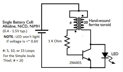
Non-Simple Jouel Thief, 1.20V, 2N4401, White LED, 495-3847-ND, 30 gauge Wire
With these tests I started using a new Inductance/Capacitance meter I picked up at: AADE in kit form. He also sells it completely built. I put it together in less than two hours one afternoon. * The simple joule thief, 20 X 20 loops, took up the complete circumference of the toroid. Loops were then removed from the short side (the end going to the base of the transistor), but the loops were not compressed until the end when the best number of fewer-to-maximum number of loops, 8 X 20, was discovered. This caused the joule thief to use the lowest current. Only the data for the 8-loop version with the excess wire removed was kept. When searching for the best version of the joule thief inductor, I measured just the currents for 9 loops, 36.1 mA, then 8 loops 35.5 mA, and last for 7 loops which was 36.0 mA. I also switched which number of loops went to the collector and base of the transistor which is colored in red to show how bad it is to get the wiring wrong. Getting the wiring backwards more than doubled the average current used by the circuit, shown in the RED row. Conclusion: While the "simple" joule thief is easier to make, one can make the joule thief more efficient (use less current), by removing some windings from the inductor that goes to the base of the transistor. The best in this case turned out to be 8 loops by 20 loops, with the eight loop end going to the base of the transistor. With this reversed, the 20-loop end going to the base of the transistor, the circuit used far more current. The ratio is 8:20 or 4:10, or 40%. We now know two things:
Next I tried 12 loops and then removed loops for the base of the transistor section to see if the current could be lowered any more while maintaining the LED brightness. Using 12 loops and starting with 8 loops for the base of the transistor.
Looking at the ratio of loops to the base to loops to the collector gives around 40%, 0.40 for the (8:20) 8 loops (to the base) by 20 loops (to the collector), and 0.417 or 41.7% for the 5:12 loops. The lowest current use is when the loops are in a ratio of 40 - 42%. Much above or below that is out of the sweet spot. On the low end, 33 - 35% or 1:3, 4:12, and 7:20 gets worse and on the upper end, 45 - 50% or 9:20, 6:12 or 1:2 gets worse. If the lowest current is wanted, it looks like we'll need to increase the collector number of loops to the max we can put on any particular toroid, perhaps 40 for the collector and then around 16 loops for the base of the transistor for a 10mm diameter toroid. Since it was easier to try fewer loops rather than more, I added two tests with 10 and 5 loops for the collector. I also thought I noticed an anomaly with one of the things I thought I'd just learned, namely, that more loops lowers the current and fewer loops increases the current. Looking at the grid of data below, we can see that, in fact, there is an anomaly around 10 - 12 collector loops. These were both lower than using 20 loops and, in fact, the 5/12 loop test used about 20% less current. It looks like I'll have to try 2/5 loops and then I'll try 12/30 and 16/40. Comparing collector loops from 20 to 5 and base loops ~40% the number of collector loops.
After doing the 12/30 test, I found that there wasn't enough room on the toroid for the 16/40 loops test and so I decided to end the tests at 30/12. The LED looked as bright and was only using ~20mA. I also tried 11/30, ~21.3 mA and 13/30, 19.2mA to confirm that 12/30 was the best. As can be seen, it turned out that one more loop 13, gave a slightly lower value so we now see that the best ratio is a bit above 40%. Right now the best data suggests about 43.3% or 13/30. I didn't leave enough wire to do another complete loop but did manage almost a complete loop, and the current went down a bit more to 19.0mA so I suspect that 14/30 would be the best and the ratio is 46.7%. It seems that the numbers are not perfect for whatever reason. In the original data using 20 loops and removing loops, I found that 8/20 or a ratio of 40% was the best, and even one more at 9/20 or 45% was worse. Yet, using 30 loops, I found that 14/30, a ratio of 46.7%, was the best, and just a little better than 13/30 at 43.3% which was better than the expected best at 12/30 or 40%. How to wind the toroid for the lowest current usage As in antenna building, it is always easier to remove some wire to make the antenna shorter than it is to put more wire on to make it longer. So, since we now know that the lowest current is achieved by using 40 - 47% as many loops for the base coil as for the collector coil, this should be easy. Starting with 50%, the number of collector coil loops for the base, coil loops can be removed from the base coil until the lowest current usage is found. Start by measuring the current, then remove loops from the base coil one at a time until the lowest current is passed. Next, add one loop back to the base coil to get back to the lowest current. Now cut off the excess wire. Example: we want to make the best inductor using 30 loops for the collector. This means we start with a piece of wire long enough, with some extra, to wind 45 loops on the toroid. We first start with some extra extending out and wind 15 loops, then fold the remaining wire to be wound and leave some extra for the transistor base coil; now loop the folded wire 15 more times. Now, cut the folded end and connect the end of the transistor base section to the beginning of the transistor's collector coil section. Starting with 15 loops for the base section and removing one loop at a time, measure the current each time until the lowest current usage has been found and passed. Then, add the one loop back to get back to the lowest current. Remove all the excess wire and the coil is done. Two Batteries Tests I wanted to see how long two batteries measuring less than 0.5 volts each would run a Joule Thief circuit when used together to produce about 1.0 volts. After one battery gets down to about 0.30 Volts most of these Joule Thief circuits stop working. Even before they stop working, the LED will become very dim and isn't of much use at around 0.45 Volts, as measured during operation in the particular circuit. I tried a number of times to select similarly-depleted AAA and AA batteries. I picked two nearly-depleted batteries at around the same depletion level and paired them together to see if I could get more use out of them and, if so, for how long. I found that most of the time, ~80%, I really hadn't manage to select two batteries with almost identical depletion levels. When these two batteries were put together, in series, they worked together for a very short length of time, less than two or three hours, before one of the batteries was down to 0.00 volts and the one battery suppled all the current. When I finally managed to get two batteries together which were very similar, they were both down to 0.2X volts within 24 hours, so there is more life left and, depending on the task at hand, they may last 24 - 48 hours. For lighting purposes, it's probably less than 24 hours. Perhaps more than 24 hours when used to charge other batteries until the "dead" batteries are useless. The Joule-Thief Power Supply I had a small flickering LED candle-flame simulation device that used a 3V #2032 battery. It lasted a number of evenings but I was wondering if I could replace the 2032 with a single AAA or AA battery and a joule thief (JT) circuit. The problem I saw here was that the JT was a pulsed voltage source and not a real steady voltage source. A constant/steady voltage source was needed for this application. After a number of tests with removing the LED and using various capacitors, I learned that it was possible to increase the pulse duration but it was not possible to decrease the off time in this manaer. Re-enter the diode... I figured that a diode was needed to allow the current to flow into the capacitor but not back out of it in order to charge up the cap to the required 3 Volts. I initially used a 1N4001 diode and this worked just fine. However, I then looked at the circuit and realized that if the LED was using ~ 3 Volts and ~ 20 mA for each pulse, why should I use a 1N4001 and get nothing, when using the LED might give some light while charging the cap. I tried this and it did work in that way. The LED lights up as it did before, but instead of the current going back to ground, it now goes into the cap which then supplies the voltage and current to run the second LED circuit to flicker its LED to simulate a real candle flame. Capacitor C1: I've tested everything from 100 μf to 100 milli Farads (0.100 F) and the one I liked best, that I had on hand for this task, was 0.047 F (47 milli Farads). This cap kept the voltage at about 2.5 Volts and was able to supply the needed current for the flickering LED. While running, the circuit measurements were: AAA Battery at 0.98 Volts AAA Battery current ~ 70 mA Output voltage ~ 2.5 Volts Output current 1.7 - 4.0 mA NOTE: The Output voltage/current is the voltage and current supplied to the Flickering LED battery compartment by the JT circuit. The time from first turning it on until the flickering candle LED starts working for this cap is about 5 seconds, and after the battery power is disconnected, the cap continues to operate the flickering LED for about 10 - 15 seconds. 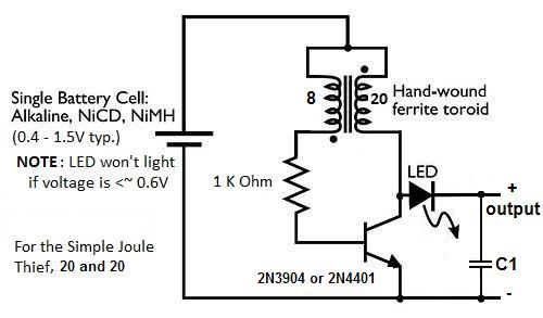
Core: #3849, 44 Loops, Supply voltage: 1.1V
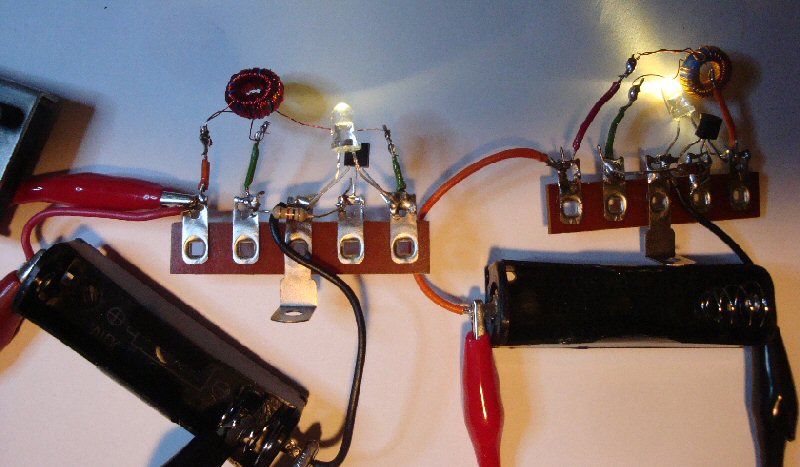
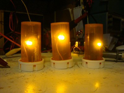
Comments: The 4401 transistor made the LED brighter than the 3904 did so if brightness is a factor then use the 4401 at the cost of using about 2.6 time more current. If longevity is a consideration use the 3904 which uses far less current at the reduced brightness. I also noticed, that for some reason, the frequency (when using the 3904 transistor) was not nearly as stable as when using the 4401 transistor. The variation was as much as 2 kHz. This did not seem to change the current usage very much ~ + or - about 0.1 mA, or the peak voltage, so I guess it's nothing to be concerned with. It could also have been a difference with the connections in the breadboard. Here's a practical application of the simple joule thief. I needed three simulated candles for three widows which had no easy way to get AC power to the "candles." Here you can see the three simulated LED candles I made with salvaged ferrite cores. 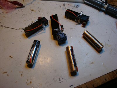
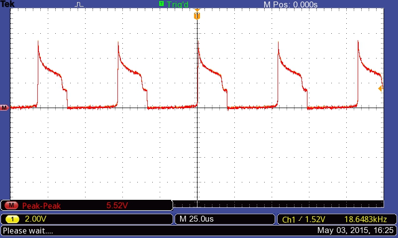
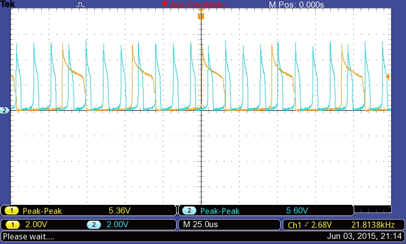
Also see the LED Tester built from this basic circuit. Low Voltage Battery Traces: Batt~0.57V, 0.4V/Div & Batt~0.41V, 100mV/Div @ 10μs, Amber LED 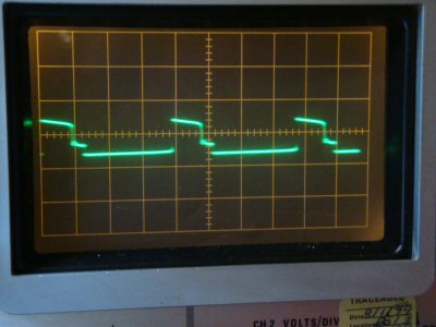
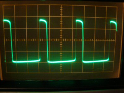
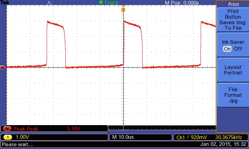
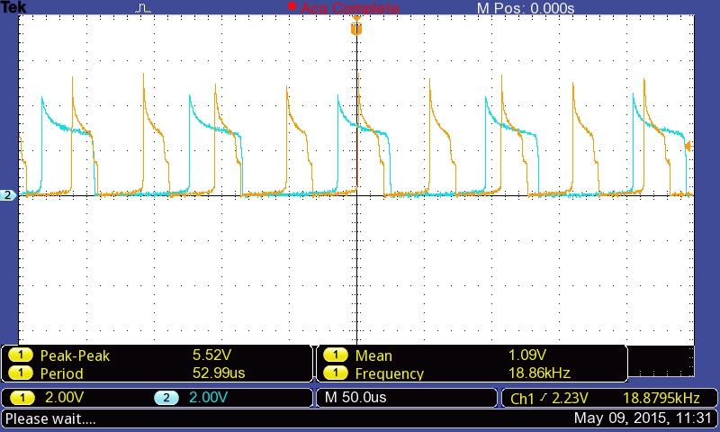
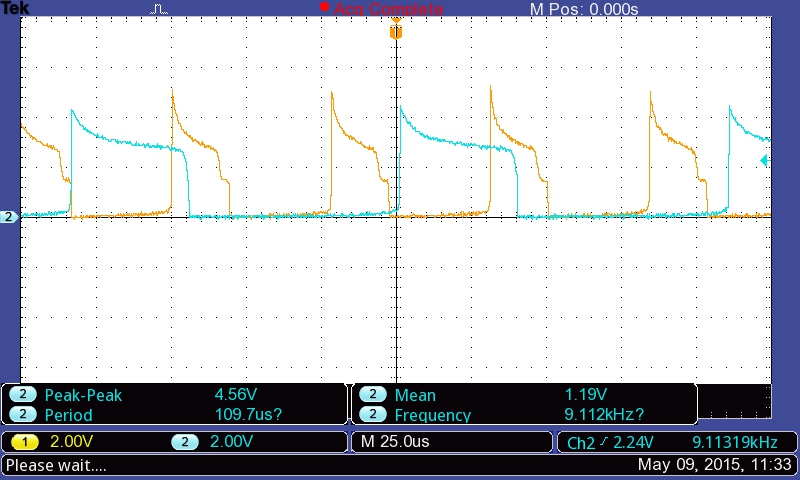
Some words on the Parts UsedThe LEDs were salvaged from two solar walkway lights that had died, so I expect that whatever they were, they probably came from the same batch of LEDs the manμfacturer used. I do not know a part number or the expected mcd (millicandela) value. The measurements/values shown are the ones caught when I pressed the hold button on my scope. The current did not seem to be changing over the few minutes I observed my Beckman 3010 multi-meter, but the frequency kept climbing until it stabilized within +/- 20 Hz. The peak voltages were also constantly in flux by about +/- 0.2 Volts. The input voltages were not exactly the same. I adjusted the voltage to the non-simple version to 1.100 Volts, measured with the Beckman meter, and the input to the simple joule thief ended up as 1.070 Volts. Some Other Joule Thief ProjectsThe Joule Thief Circuit using Solder Islands Cut From a Wax Paper Cutting Strip. The night-light in a Box, using either a "dead" AAA Battery or a "dead" AA Battery. Added Capacitance Tests, 01/25/2020Dean, who caught an error on my "Schematic 1: Center tap Circuit" on the "Center-Tapped Joule Thief Plus" page also mentioned that one can slow down the frequency of the basic Joule Thief by adding a small cap across the resistor. below you can see the new basic Joule Thief circuit and below that are two images from the oscilloscope.--- No Added Capacitor used --- --- 0.015 μf Capacitor used --- From these two traces it can be seen that the frequency dropped from ~ 19.6 kHz to ~ 16.7 kHz or by approximately 3 kHz. But also notice that the peak voltage dropped from about 5.1 Volts to about 4.3 Volts. As I added more capacitance not only did the frequency drop but so did the voltage and the brightness of the LED. The breaking point for brightness seemed to be around 0.022 μf for my circuit. At this point the brightness was unacceptable as a night-light. I continued to add capacitance up to about 0.068 μf at which point the frequency was around 55 Hz and wasn't very stable either. I'm not so sure that this is a good trade-off to increase the life of a dead battery. I like to use these circuits for child night-lights and small flashlights they can use. For me the brightness is an important quality. If however brightness is not that important to you then you can add more capacitance. I was using a capacitance break-out box so perhaps with a capacitor soldered in, the trace would improve to the point of not having that funny second lower trace and perhaps the brightness and voltage would not decrease as much. My circuit was all soldered except for the capacitor, LED, and the power connections. All of these had wires coming out of the board to a proto-strip. One other difference was that the inductor also had a center tap coil as well as the normal Joule Thief coils and while this did not seem to effect the basic Joule Thief trace, perhaps it does effect the trace when a cap is added. The center-tap coil wires were left unattached, just floating in the air. Some Other ProjectsBeyond the Simple Joule Thief - This describes my use of the better Joule Thief circuit with one additional modification and some bogus 9800mAh batteries in something useful.I also made a replacement Car boot/trunk lighting, Ham Shack Lighting, LED Tester, and a Piano Light "bulb" out of two LED modules with three LEDs in each of them, the base of a dead LED light bulb, and the circuit from inside a 12V, 500mA switching power supply. The 5 LED night-light that plugs into the AC wall socket and uses about 250mW (about 1/4 Watt.) NEW: Building a Center-Tapped Joule Thief for Christmas Flickering Candle LEDs Questions, Comments? Send me an email (Please include what page you were on. This is the Joule Thief page.) Some Good Joule Thief ArticlesHere are a few of the better articles I've come across explaining the Joule Thief:Title: Joule thief Link: http://en.wikipedia.org/wiki/Joule_thief Synopsis: A good explanation, schematic, and O-scope trace which shows what my scope showed. Title: MAKE A JOULE THIEF Link: http://www.bigclive.com/joule.htm Synopsis: Clearly shows how to connect the windings of the ferrite cord inductors. Title: Making A Simple Joule Thief (made easy), by ASCAS Link: http://www.instructables.com/id/Making-A-Simple-Joule-Thief-made-easy/ Synopsis: The one I used to make mine, no explinations but it works. Title: "Joule Thief" Circuits, crude to modern... by Dave Kruschke Link: http://www.instructables.com/id/Joule-Thief-Circuits-crude-to-modern/ Synopsis: Here Dave shows how this circuit works using a mechanical switch! Title: Bifilar coil Link: http://en.wikipedia.org/wiki/Bifilar_coil Synopsis: How to wind it & the different connections Title: The Joule Thief! Link: http://www.r3uk.com/index.php/tech-tips/43-electrical-tomfoolery/179-the-joule-thief Synopsis: R3UK has some very good explinations, experiments, and results. Ideas on better transistors to use than the 2N3904 Questions, Comments? Send me an email (Please include what page you were on. This is the "Joule Thief Information" page.)  Return to:
previous page
Return to:
[My Home page]
Return to:
previous page
Return to:
[My Home page]
|